Voltera
Metron Expander
1Introduction
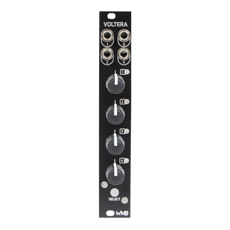
Voltera is a 4HP CV expander for Metron. It adds four bi-polar control voltage outputs, four knobs for entering and editing voltage data, and four bi-color track LEDs. Voltera is a “last event” sequencer: an output always holds the voltage of the last event sent to it, and a step only updates the output when the sequencer plays that step. Multiple Voltera and Metron units can be chained together.
2Rear Connections
- EXP: 2x proprietary bus connectors for connecting multiple Metron and Voltera units.
- Memory Card: Voltera requires a memory card to be present at all times.
- Power: Voltera uses a 16-pin power connector. No power is consumed from the +5V rail.
3Front Panel Overview
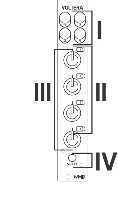
- Outputs: 4x bi-polar CV outputs. Ranges from -5V to 5V.
- Track LED: 4x bi-color LEDs associated with the track label.
- Track Knob: 4x potentiometers for entering data and selecting tracks.
- Select Button: Backlit momentary push button used for output takeover and viewing set voltages.
4Connecting Voltera and Metron
The EXP headers on the back of Metron and Voltera make it extremely simple to connect expanders to Metron. Connect one 8-pin ribbon cable, supplied with Voltera, to either of the two EXP headers on Metron. Be sure to orient the red stripe toward the white dot printed next to the “EXP” label. Connect additional Voltera units either to each other or to the second EXP header on Metron. Finally, place the EXP TERM covers on open headers. Indicators must be facing the same direction (down) on the covers and PCB. It is generally best practice to string or chain Metron and Voltera units one by one, and place EXP TERM covers at either end of the string.
If a visual explanation would be more helpful, check out the Voltera playlist on our YouTube channel.
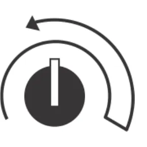
5Track Select “Turn” Gesture
Because there are no individual track select buttons on Voltera, the knobs are used to select each track using the “turn” gesture. Perform the “turn” gesture by turning a knob to the full clockwise position, then a small turn back in the counter-clockwise position.
5.1Functions That Use The “Turn” Gesture
The following Metron track functions are available to Voltera tracks by using the “turn” gesture:
DUPLICATE
CLEAR
SPECIAL FUNCTIONS: PL.DUP, CONTRACT, EXPAND
Other Metron track functions like NUDGE and PTN LENGTH can be performed on a Voltera track by moving a Voltera [TRACK KNOB] or pressing the [SELECT] button, followed by the Metron [MATRIX] buttons normally associated with the mode.
6Basic Functions
Voltera is a “last event” sequencer. This means that the outputs will always hold the voltage of the “last event” sent to them. Setting a step will not send an event to the output until the sequencer plays that step.
![Metron with a Voltera attached on the right. One callout points to a Voltera knob reading “Hold the [MATRIX] and turn a [VOLTERA KNOB] to set a voltage.” A second callout points to the SELECT button reading “Hold [SELECT] to view voltages set on this Voltera. Press a lit [MATRIX] button to clear the step.”](/_astro/c-basic.BcAFCkTx_Z2oybDq.webp?dpl=dpl_Atyjt9LXJae5y51WeyiNMhx3oHri)
6.1Setting a Voltage on a Step
Set a voltage on a step by holding a Metron [MATRIX] button and then turning the [VOLTERA KNOB] associated with the output you would like to set the voltage on. The voltage or quantized v/oct value will be displayed on Metron's [CURRENT STEP DISPLAY] as well as Voltera's [TRACK LED].
6.2Voltage Display
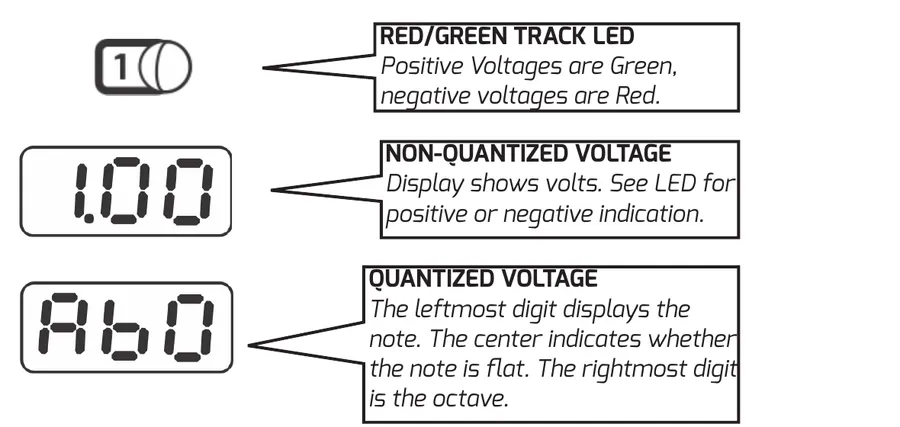
Red/Green Track LED: positive voltages are green, negative voltages are red.
Non-quantized voltage: the display shows volts. See the LED for positive or negative indication.
Quantized voltage: the leftmost digit displays the note, the center indicates whether the note is flat, and the rightmost digit is the octave.
6.3Audition Step While Setting Voltage
Pressing the [SELECT] button before or while setting a voltage on a step will “audition” the voltage of that step. The output voltage will be directly set by the knob as long as the [MATRIX] button is held.
6.4Live Takeover
Holding the [SELECT] button on Voltera before turning the [VOLTERA KNOB] will set the output to “Live Takeover.” When this is enabled the [VOLTERA KNOB] directly sets the voltage of the corresponding output, regardless of the state of the sequencer. When the user releases the [VOLTERA SELECT] button the output will return to normal sequencer-driven operation.
7Knob Input Range
Voltera offers a number of knob input ranges for more detailed entry of control voltage data. Voltera's outputs always offer a -5V to +5V voltage range. The sequence will play as it was written regardless of the current input range. Enter this mode by moving any Voltera knob while viewing Global Settings. The currently selected Voltera track will show on the COUNTER display.
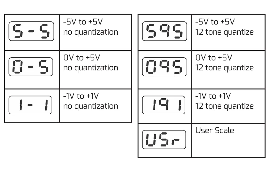
| Display | Range | Quantization |
|---|---|---|
| S-S | -5V to +5V | No quantization |
| 0-5 | 0V to +5V | No quantization |
| 1-1 | -1V to +1V | No quantization |
| S95 | -5V to +5V | 12 tone quantize |
| 095 | 0V to +5V | 12 tone quantize |
| 191 | -1V to +1V | 12 tone quantize |
| USr | User Scale | User Scale |
Voltera knob input range display codes, their voltage ranges, and quantization.
8User Scale
The Voltera user scale allows you to set a custom scale with a custom octave range per output. The user scale is saved and recalled on power up as well as when a session is saved or loaded. Active notes and octave ranges will blink with a breathing pattern.
![Metron matrix annotated for user scale editing. The top matrix row selects octaves, with the right side marked “Positive Octaves” and the left side marked “Negative Octaves,” and a callout reading “Press [MATRIX] row 1 to select a single octave. Hold a button and press another to set multiple octaves.” The lower rows form a chromatic keyboard, with a callout reading “Chromatic Keyboard sets the note mask. Active notes breathe.”](/_astro/c-userscale.Dxcp2Tb7_Z1FuBro.webp?dpl=dpl_Atyjt9LXJae5y51WeyiNMhx3oHri)
9Specifications
Dimensions:
- Width: 4HP (20.32mm)
- Height: Eurorack 3U (128.5mm Panel, 112mm PCB behind panel)
- Depth Including Cables: 43mm
Power:
- 16 pin Eurorack standard power cable
- Reverse Polarity Protected
- Do not connect power to expansion headers.
- Typical Power Consumption: +12V: 60mA, -12V: 15mA
Outputs:
- Channel Outputs 1-4: 470 ohm Impedance, -5V to +5V
- Channels are simultaneously updated.
- Channel Outputs are impedance compensated.
Regulatory:
- RoHS, CE, & WEEE Compliant
- Made with Lead Free solder and processes.
10More Features in the Metron Manual
Guess what!? There's more! Visit the Metron product page and download the updated Metron manual to find out about even more new features Voltera offers.