Time Warp
Dual Gated Voltage Slew & Envelope Follower
1Introduction
Time Warp is a dual gated voltage slew and envelope follower in a compact 4HP package. Each of its two independent channels (A and B) smooths the signal patched to its IN jack, presenting the slewed result at the OUT jack. The amount of slew can be gated on and off using the GATE inputs and INVERT LOGIC switches, and when nothing is patched to a GATE jack that channel becomes a full wave rectifier envelope follower.
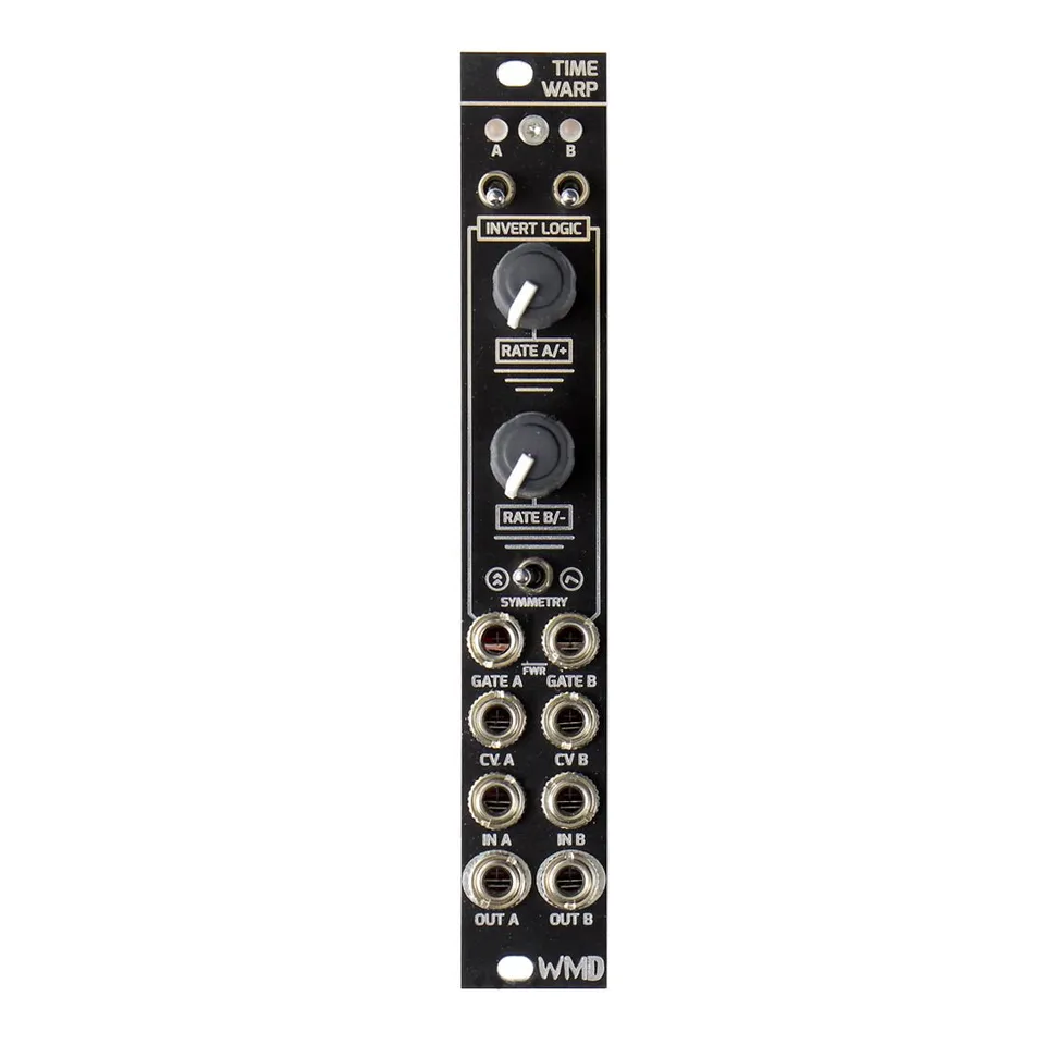
2Front Panel Overview
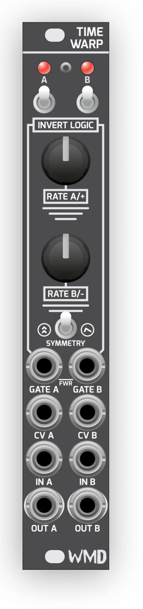
- LED: Shows the state of the slew. The LED is lit when the slew is enabled.
- Invert Logic Switches: Invert the logic of the GATE input. With the switch in the up position the slew stays enabled until the gate input goes above 3V.
- Rate Knobs / CV: Set the slew rate. Their behavior changes with the SYMMETRY switch (see Rate, Symmetry, and CV below).
- Symmetry Switch: Selects between symmetrical (independent) and non-symmetrical (shared) rate control.
- Gate: Toggles the state of the slew depending on the INVERT LOGIC switches.
- CV: Voltage control input for the slew rate.
- IN / OUT: Patch the signal you want to slew into IN; the slewed signal appears at OUT.
3Slew Inputs and Outputs
Patch the signal you would like to slew into the IN jack of a channel. The slewed signal will be present on that channel's OUT jack. The LED for each channel shows the state of the slew and is lit whenever the slew is enabled.
4Rate, Symmetry, and CV
The RATE knobs change function depending on the position of the SYMMETRY switch:
Left position — each slew is linear and symmetrical with independent controls, so RATE A and RATE B set their channels separately.
Right position — the slews switch to non-symmetrical with shared controls, where RATE A/+ sets the rising rate and RATE B/- sets the falling rate.
The CV inputs provide voltage control over the slew rate.
5Gate Inputs and Invert Logic
Use the GATE input to toggle the state of the slew, depending on how the INVERT LOGIC switches are set:
Switch up — the slew effect is enabled until the GATE input goes high (above 3V).
Switch down — a high signal at the GATE input enables the slew effect.
6Envelope Follower
The GATE jack acts as a switch for a full wave rectifier, enabling each slew to act as an envelope follower. This mode is active when nothing is plugged into the GATE jack.
7Specifications
Dimensions:
- Size: 4HP (20.32mm)
- Depth: 30mm (with cables)
Power:
- 40mA +12V
- 40mA -12V
Inputs:
- CV: 100k ohm impedance
- IN: 50k ohm impedance
- Gate Inputs: 100k ohm impedance, 2V threshold Schmitt Trigger
- Patching into the Gate input disables the Full Wave Rectifier
Outputs:
- CV Outputs: 470 ohm impedance, zero-impedance compensating buffer
- 1V/Octave no drop
- 22Vpp range
- Gain error: 0.1% maximum, 0.025% typical
- Offset error: 1.5mV maximum, 0.5mV typical