SL3KT
AB Switch With Ganged Operation
1Introduction
SL3KT is a bi-directional, CV controllable AB switch. Useful for many tasks in a Eurorack system such as sequence selecting, CV selecting, boolean logic operations, group switching, group routing, gating, waveform mixing, and so much more! High quality switching and signal path ensures your audio or CV switches fast and glitch free.
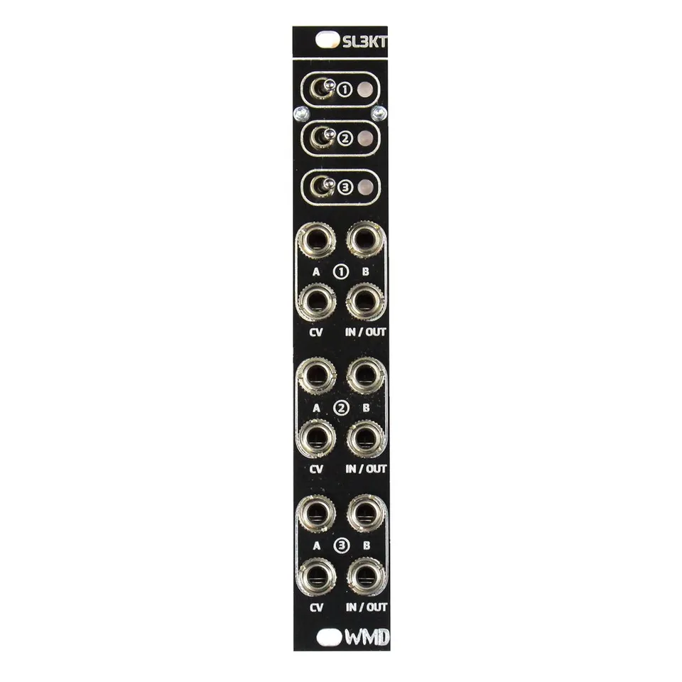
2Front Panel Overview
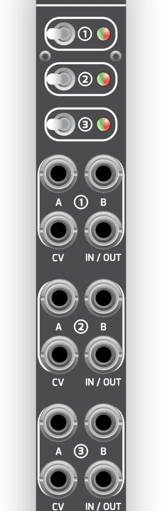
SL3KT provides three independent AB switch channels. Each channel has its own SWITCH, LED, and set of A, B, CV, and IN/OUT jacks, described below.
- SWITCH: Manual selection of the switch routing. Also inverts the logic of the CV input.
- LED: Indicates the current switch routing. The LED will be green if A is connected to IN/OUT. The LED will be red if B is connected to IN/OUT.
- CV: Voltage controlled selection of the switch routing. 3V schmitt triggered gate-high input.
- A, B, IN/OUT: The switched signal path. A and B are the two switchable connections; IN/OUT is the common connection. The path is bi-directional, so any of these jacks can be used as an input or an output.
3Signal Flow
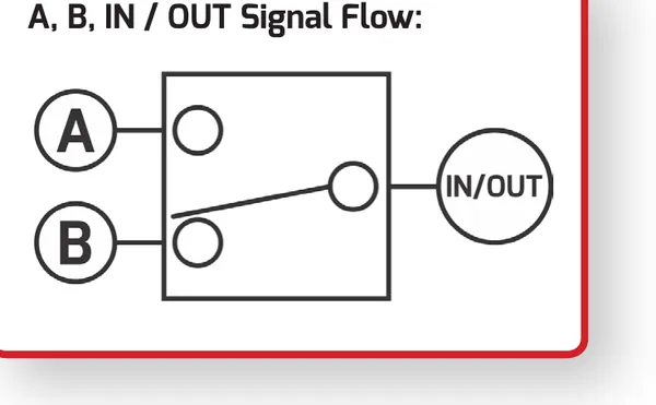
Because the signal path is bi-directional, IN/OUT can be driven from A or B (acting as a 2-to-1 switch), or IN/OUT can feed either A or B (acting as a 1-to-2 router). Use the SWITCH for manual selection, or the CV input for voltage-controlled selection.
4Suggested Patches
4.1Sequence Switch
Patch the gate and v/Oct from sequence A into the A jacks of switch 1 and 2. Patch the signals from sequence B into the B inputs. Flipping the first switch will change both switches simultaneously.
4.2Boolean Logic
INVERT — Patch a voltage offset into the A side of one switch. Patch the gate you would like to invert into CV.
AND — Patch gate one into B. Patch gate two into CV.
OR — Patch gate one into A. Patch gate two into B and CV.
4.3Waveform Mixer
Put two waveforms from the same oscillator into A and B. Place the pulse out from the same oscillator into CV. Listen to IN/OUT.
5Specifications
Dimensions:
- Size: 4HP
- Depth: 30mm (with cables)
Power:
- +12V: 10mA
- -12V: 10mA
Inputs & Outputs:
- All CV Inputs: 100k ohm impedance
- A / B / IN / OUT: 20 ohm impedance
- Bi-directional
- Negligible drop on 1V/Oct signals.
- CV: 3V schmitt triggered gate-high input.
6More Information
Visit the SL3KT product page for demo videos and more details.