Skorpion
Waveform Reanimator
1Introduction
At its most basic, Skorpion is a wavefolder. Signal goes into the IN jack, is processed, and then spit out of OUTL / OUTR. Patch just this and start turning knobs to get going. Skorpion is designed for experimentation, so please patch courageously and enjoy the magic.
1.1Theory of Operation
The signal at the IN jack gets analyzed by 8x comparators set by the sliders (THLDs). The VECTOR CORE is a signal generator that has a SLOPE, and a TARGET voltage it's headed towards — this is the signal at the OUTL / OUTR jacks. Each time a comparator gets crossed, the VECTOR CORE reverses direction, creating wavefolding influenced by the input signal, but not a gained up version of it. SLOPE is affected by SHAPE, creating complex curves.
The sliders are a digitally controlled analog UI section for setting THLDs, TRGTs, and modulation (MACRO SETUP). The final piece of the sound is the OUTPUT stereoization circuitry: an ultra short delay to enhance the stereo field, with a switchable mid/side matrix to keep the low end centered, and push the high frequencies to the sides.
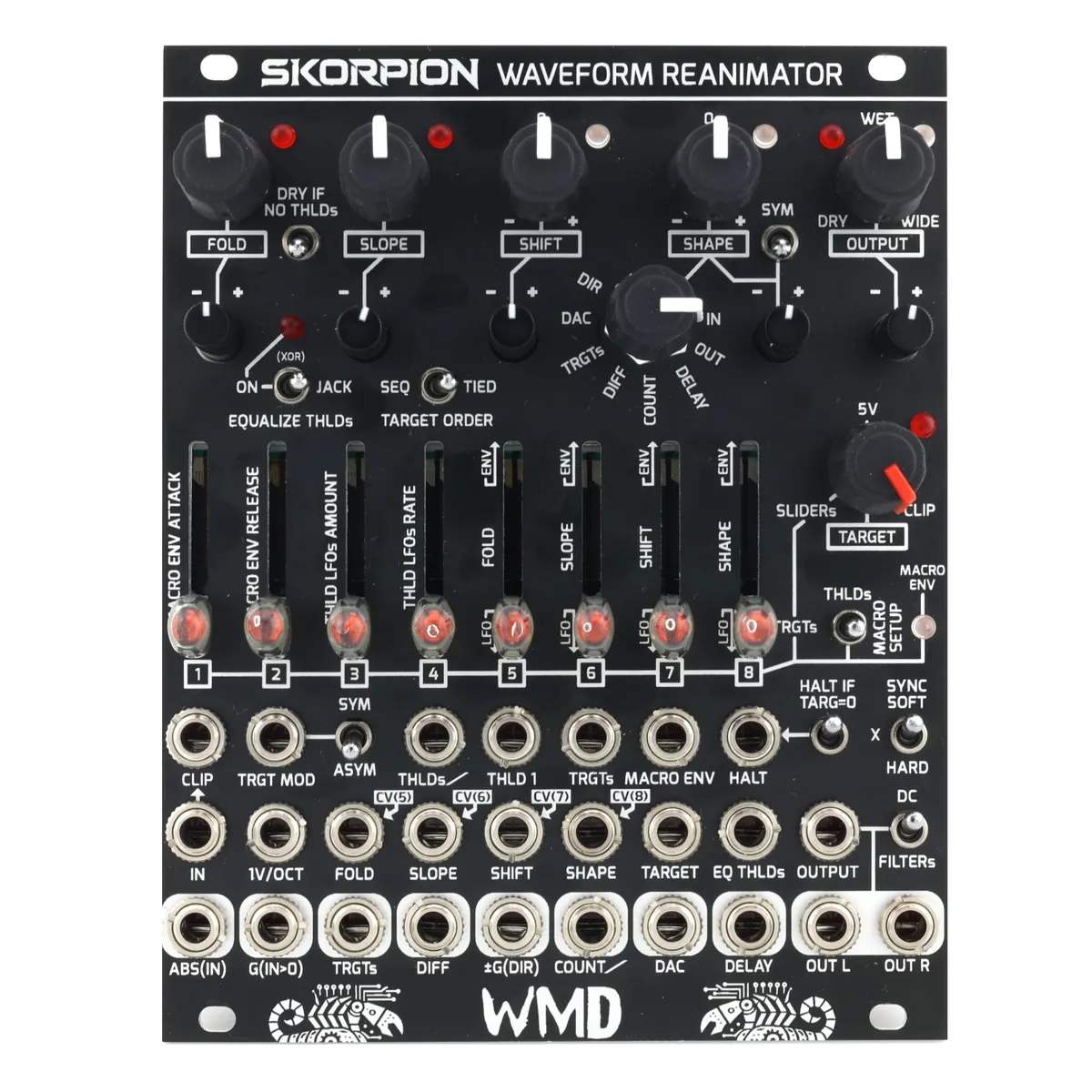
2Front Panel Overview

3Main Controls
3.1FOLD
Controls the amount of wavefolding, amplifying the input signal against the comparator stack. CV controllable with attenuverter and jack.
3.2SLOPE & 1V/OCT
SLOPE controls the basic rate of change of the vector core; higher slope means that the signal goes further, faster, creating more harmonic content. CV controllable with attenuverter and jack.
1V/OCT controls slope and is necessary for equal timbre across different notes.
3.3SHIFT
Pushes the IN signal up and down against the comparators, creating asymmetry. Slow modulation here produces a frequency shift effect. Sums with the IN signal. 0V (no shift) at 12 o'clock. CV controllable with attenuverter and jack.
3.4SHAPE
Modulates the SLOPE with different sources of feedback. No feedback at 12 o'clock. SYM up makes the modulation symmetrical for the positive and negative portions of the signal at IN. CV controllable with attenuverter and jack. The SHAPE source is chosen with the rotary switch:
- IN: The input signal directly.
- OUT: The output signal; creates LOG/EXP type feedback.
- DELAY: The delayed signal from WIDE, only active when OUTPUT is between 12 o'clock and fully clockwise.
- COUNT: The staircase count of the number of active comparators.
- DIFF: The difference between the target and the actual value of the vector core. Creates spikey harsh timbres.
- TRGTs: Control the slope of each individual segment using the TRGT sequencer.
- DAC: A weighted version of count. More subtle than count.
- DIR: +/-5V direction signal, used for skewing the output.
3.5TARGET
Controls the vector core's destination voltage.
- 5V: Static voltage, creates the squarest waveforms.
- CLIP: This is the input waveform, so the output will overlay the input.
- SLIDERs: Uses the sliders as a sequencer, applying a user-specified voltage as a target as each threshold is crossed.
3.6OUTPUT
DRY ↔ WET on the lower half, and WET ↔ WIDE on the upper half. CV controllable with attenuverter and jack. WIDE fades in the MID/SIDE network. See the DELAY output jack for how the delay functions. The OUTPUT switch sets the filtering:
DC is the direct signal, no filtering.
FILTERs adds a LP/HP network. Frequencies below 240Hz are not delayed and sent to mid. Frequencies above 240Hz are delayed, and the difference is sent to the sides, the sum is sent to the mid.
4Threshold Controls
4.1EQUALIZE THLDs
Forces equal threshold intervals, regardless of CV and slider settings. Makes the timbre sound more like a classic wavefolder. The LED is ON when thresholds are equalized.
ON: Toggle forces thresholds equalized. Jack ignored.
XOR (mid): thresholds equalized; a high signal at the jack turns this off.
JACK: thresholds-equalized disabled; a high signal at the jack turns this on.
4.2DRY IF NO THLDs
If no thresholds are active, this will force the output to be the dry signal. The vector core will attempt to follow the signal at IN. SLOPE still applies, and will sound like a low pass filter if the input signal has more harmonic content than the SLOPE setting. Use this to ensure you always get signal if heavily modulating FOLD.
4.3SYNC
Forces the vector core to reset at zero crossings of the IN signal.
SOFT: ramps towards 0V at the current SLOPE rate.
X: no sync.
HARD: fast reset to 0V.
5Sliders & Macro Setup
The SPRING TOGGLE (to the right of the sliders) and the slider bank work together to form the user experience of the thresholds, targets, and modulation within Skorpion.
5.1Sliders
The bank of sliders controls a few different aspects of Skorpion:
THLDs (thresholds): default function.
TRGTs (targets): by holding the spring toggle to the left.
MACRO SETUP: by holding the spring toggle to the right.
In all contexts, the sliders have a small hysteresis, requiring a little movement for them to start changing the parameter. This prevents parameter jumping when context switching. The LED on each slider will always reflect the current state in the current context, selected by the spring toggle.
5.2THLDs (Thresholds)
The default mode (spring toggle is in the middle position). The slider LEDs display the current threshold voltage by brightness. A threshold is a voltage where a fold will occur; all eight can be controlled individually, with CV, and modulation. CV that affects the THLDs:
THLDs/ : a weighted CV input, affecting all thresholds. THLD1 gets CV ÷ 2^7, THLD2 gets CV ÷ 2^6, etc., to THLD8 which gets CV ÷ 1.
THLD1: this jack controls the first threshold.
EQ THLDs: this jack (depending on the switch) will control whether the sliders are used for the thresholds, or whether they are all equal.
All CVs support audio rate modulation.
5.3TRGTs (Targets)
Hold the spring toggle to the left to edit the targets. This context changes immediately. Targets are voltages that the vector core can aim to, selected by which thresholds are active. The 8 targets form an 8 step voltage controlled sequencer. How targets are used:
TARGET: when between SLIDERs (the TRGTs sequencer) and 5V, the TRGTs control the destination voltage of the vector core.
SHAPE: when the rotary switch is selecting TRGTs, the TRGTs sequencer can be used to shape each segment of the folded waveform, modulating the slope.
TRGTs output jack: an open-ended way to have the TRGTs sequencer modulate anything.
Additionally, using the TRGTs input jack, all targets can be modulated simultaneously.
TARGET ORDER selects how a target is chosen:
SEQ: Target is selected by count of active thresholds.
TIED: Target is selected by most recently crossed threshold.
5.4Macro Setup & Macro Envelope
This is the internal modulation section of Skorpion. The macro envelope is an attack–sustain–release envelope that controls the amplitude of every LFO in the system, fading it in and out. Attack and release are controllable. The gate can be from the spring toggle or the MACRO ENV jack.
Spring toggle gestures:
TAP RIGHT: A quick tap and release to the right will enable/disable the Macro Envelope.
HOLD RIGHT: Hold to the right to change the parameters of the Macro Modulation section. The sliders change context after 1 second of holding. The switch must remain held while changing Macro Settings.
MACRO ENV LED:
RED: Gate; indicates that the envelope is on, either from the MACRO ENV jack or the toggle tap.
BLUE: Fades in and out showing the state of the MACRO ENVELOPE.
MACRO SETUP slider operations (spring toggle held right):
- MACRO ENV ATTACK: 50ms to 600s attack time.
- MACRO ENV RELEASE: 500ms to 600s release time.
- THLD LFOs AMOUNT: Maximum amplitude of the LFOs that modulate the thresholds.
- THLD LFOs RATE: The base rate of the LFOs that modulate the thresholds. 0.0016Hz to 6Hz.
- 5–8: HARDWARE NORMAL MODULATION (FOLD, SLOPE, SHIFT, SHAPE): These sliders control LFOs or ENVELOPES, selectable with a quick gesture. TOP → BOTTOM within 0.6s selects LFO mode; BOTTOM → TOP within 0.6s selects ENV mode. LFO: 0.0016Hz to 6Hz, unipolar, amplitude controlled by MACRO ENV. ENV: 50ms to 600s envelope, gate controlled by MACRO ENV gate, but amplitude is not modulated by MACRO ENV. The signal routes to the corresponding jack normal CV(5-8).
5.5Saving Settings
All settings are saved after 1 minute of inactivity on the sliders or spring toggle. These settings are recalled on power up. MACRO ENV will always be OFF when powered on.
6Other Functions
6.1HALT IF TARG=0 & HALT Jack
HALT IF TARG=0: When a target is set to bottom (0), this switch allows that segment of wavefolding to halt (stop moving) for just that segment, creating squares in the timbre. This normals to the HALT jack.
HALT jack: stops the vector core from moving, forcing it to remain at the current voltage. Audio rate modulatable.
6.2CLIP & TRGT MOD
CLIP: The input signal normals to the CLIP jack, and this shows up at the clockwise side of the TARGET pot. Use the CLIP jack to force Skorpion to clip to a different signal than the input. Try percussion or other synth lines here for experimental results.
TRGT MOD: This directly influences the output of the TARGET pot, allowing for overlaying another signal as the target voltage of the vector core.
SYM: The TRGT MOD signal is full-wave rectified so it operates symmetrically on the waveform.
ASYM: The TRGT MOD signal is sent through straight, creating asymmetry in the modulation of TARGET.
6.3Auxiliary Output Jacks
The bottom row of jacks are useful modulation sources that Skorpion generates. They can all be used to self-modulate Skorpion, or patch to other modules, providing endless experimentation and possibility.
- ABS(IN): The full-wave rectified version of the IN signal. Useful for experimental modulation.
- G(IN>0): Gate signal that is 0V when the signal at IN is below 0V, and +5V when the signal is greater than 0V.
- TRGTs: Direct connection to the output of the target sequencer. Use it as an 8 step wave table oscillator, or for modulating parameters one threshold at a time.
- DIFF: The difference between the TARGET voltage and where the vector core is. It always slopes towards 0V and is typically very high in harmonic content.
- ±G(DIR): Bipolar gate output: +5V when the vector core is going up, -5V when it is going down.
- COUNT: Creates a staircase for each active threshold. From 0–4V, each threshold adds 0.5V.
- DAC: A weighted version of count (full scale 0–4V): THLD1 adds 1÷256 of full scale, THLD2 adds 1÷128, THLD3 adds 1÷64, THLD4 adds 1÷32, THLD5 adds 1÷16, THLD6 adds 1÷8, THLD7 adds 1÷4, and THLD8 adds 1÷2 of full scale.
- DELAY: The delayed waveform produced by the WIDE portion of OUTPUT. If OUTPUT is below 12 o'clock, there will be no output. Fades in between 12 o'clock and 12:30. Increases delay time until 3 o'clock. Beyond 3 o'clock, delay time and slow modulation depth and rate are increased to 5 o'clock.
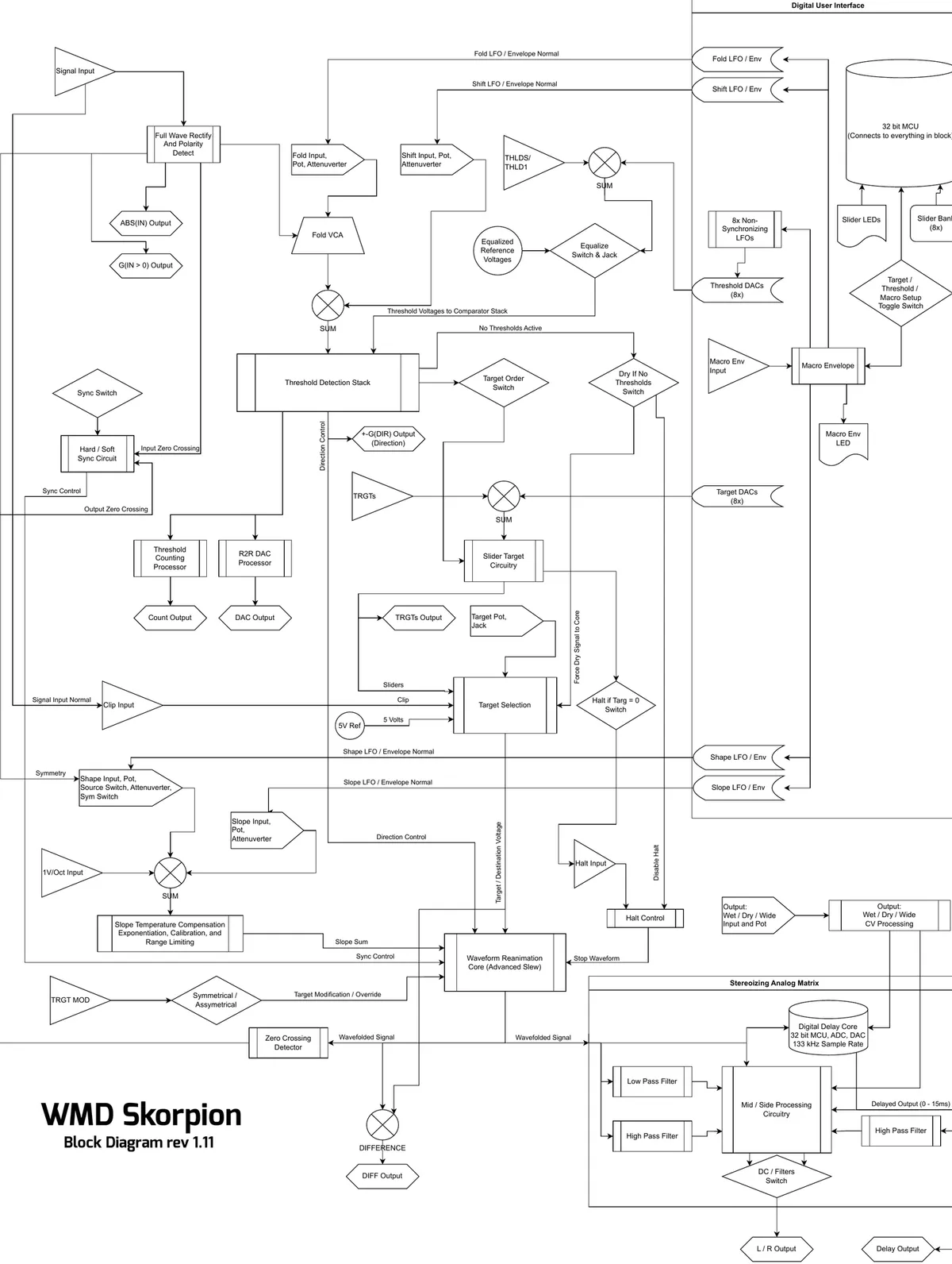
7Block Diagram
8Specifications
Dimensions:
- Size: 20 HP
- Depth: 38mm (with cables)
Power:
- +12V: 200mA
- -12V: 160mA
Inputs:
- IN: 100kΩ impedance, +/-5V nominal range
- 1V/OCT: 3MΩ impedance
- TRGT MOD: 20kΩ impedance
- All other CV/Gate inputs: 220kΩ impedance
Outputs:
- 1kΩ impedance
Internal Modulation:
- LFO Rate: 0.0016Hz to 6Hz
- Envelope Time: 50ms to 600s
- Mid/Side Network: 240Hz crossover
- Slew Rate Max: 0.4V/µs
- Audio Path: analog, except for Delay
Delay Time:
- Fade In: 80µs to 1.8ms (OUTPUT from 12 o'clock to 12:30)
- Until Modulation Starts: 8.2ms (OUTPUT at 2:15)
- Max Time: 14.4ms +/-3ms at 2Hz modulation rate
9A Note From William
Skorpion started in early 2020, before the pandemic, a literal shower thought on wavefolding. It has been an on/off passion project through a lot of turmoil. I'm grateful to have it done and to have had the opportunity to see the concept through to its full potential.
I've done a few other wavefolders over the years, notably the WMD/SSF Ultrafold, which is based on the Buchla wavefolder. A great sounding design but is so nonlinear that it's more of a distortion. I needed to create something different, high precision and still analog, and the control scheme for Skorpion was born from the old Multimode Envelope (MME) – basically a transistor controlled triangle oscillator with direct control over up and down rates, feedback for shaping, and comparators for determining if the envelope got where it needed to go.
The advancements in VCA technology over the last 10 years allowed for Skorpion to achieve nearly perfect slope over temperature calibration, tested to 14 octaves. It's bonkers linear and stable, so it handles tons of heavy feedback and the fast switching of thresholds firing from cymbals. The whole circuit is a mass of CMOS logic and analog support. I'm really proud of this absurd exploration into analog, the development process was filled with experimentation and tinkering, like the good old days of designing Synchrodyne and the PDO. I'm so glad to be back doing esoteric analog circuitry.
This design achieves some highly technical synchronous analog perfection, different from my older designs that were tinkered with and voiced just enough to get them to work. It's empowering to see my skills and intuition for electronic design growing over the last 20 years as I've embraced precision in design.
My hope in creating Skorpion is that you lose track of time creating new sounds that fuel your artistic fire. I find a great deal of joy in knowing my odd creations inspire other creatives to make amazing art and music.
Thank you for the continued support, I'm so grateful to the community for finding value in my art.
— William