PM DB25 MKII
Balanced Output Expander for the Performance Mixer
1Introduction
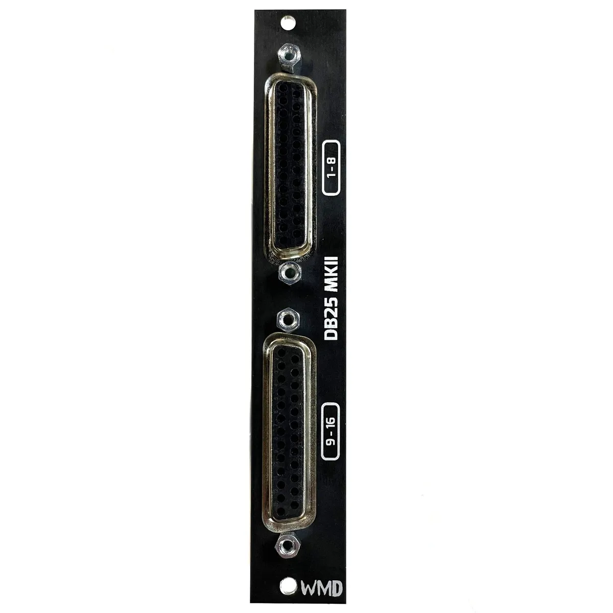
The PM DB25 MKII is a balanced-output expander for the WMD Performance Mixer. It breaks out every mixer channel onto two standard DB25 connectors, letting you connect the entire mixer to an audio interface, recorder, or external mixer with a single DB25 snake instead of a tangle of individual patch cables.
The two DB25 jacks carry 16 balanced outputs in total: the upper connector is labeled 1-8 and the lower connector is labeled 9-16. This guide walks through connecting the expander to your Performance Mixer (and, optionally, to PM-Channels) and includes a snake cheat sheet mapping each DB25 pin to its mixer channel.
2Connecting to the Performance Mixer
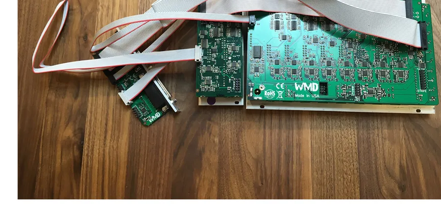
Use these two steps to connect the DB25 expander directly to a Performance Mixer when you are not using PM-Channels. The included ribbon cables are very long, so you can place the DB25 expander anywhere in your system that is convenient.
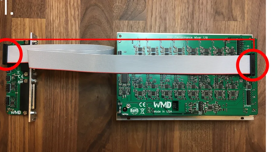
2.1Step 1: 20-pin ribbon cable
First, connect the far-right 20-pin connector on the Performance Mixer to the 20-pin header on the very top of the DB25 expander with the included 20-pin ribbon cable. Orient the red stripe toward the bottom of both modules.
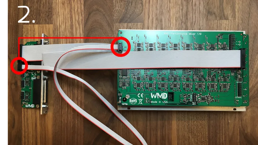
2.2Step 2: 6-pin ribbon cable
Next, connect the top-most, far-left 6-pin header on the Performance Mixer to the 6-pin header on the DB25 expander directly below the 20-pin header, using the included 6-pin ribbon cable. Orient the red stripe toward the bottom of both modules.
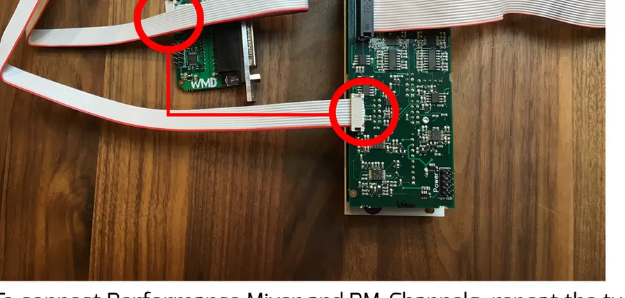
3Connecting PM-Channels
To use the DB25 expander with PM-Channels, first connect the Performance Mixer to the DB25 expander using the two steps above. Then connect the included 10-pin cable from the left-most, middle header on PM-Channels to the header that is second from the bottom on the DB25 expander. Both are labeled accordingly. Orient the red stripe toward the bottom of both modules.
4Snake Cheat Sheet
Use the tables below as a reference for which Performance Mixer channel appears on each channel of your DB25 snake. The two DB25 connectors are labeled 1-8 (top) and 9-16 (bottom). All outputs are balanced and pre-fader. We recommend a DB25-to-XLR or DB25-to-TRS snake to connect to your mixer, interface, or recorder directly.
| Snake Channel | Performance Mixer Channel |
|---|---|
| 1 | Master LEFT |
| 2 | Master RIGHT |
| 3 | Channel 1 |
| 4 | Channel 2 |
| 5 | Channel 3 |
| 6 | Channel 4 |
| 7 | Channel 5 |
| 8 | Channel 6 |
DB25 TOP connector: snake channel to Performance Mixer channel mapping.
| Snake Channel | Performance Mixer Channel |
|---|---|
| 1 | Channel 7 LEFT |
| 2 | Channel 7 RIGHT |
| 3 | Channel 8 LEFT |
| 4 | Channel 8 RIGHT |
| 5 | Channel 9 LEFT |
| 6 | Channel 9 RIGHT |
| 7 | Channel 10 LEFT |
| 8 | Channel 10 RIGHT |
DB25 BOTTOM connector: snake channel to Performance Mixer channel mapping.
5Specifications
Outputs:
- 16 balanced outputs across two DB25 connectors (labeled 1-8 and 9-16)
- Master LEFT/RIGHT and Channels 1-10 (Channels 7-10 split LEFT/RIGHT)
- All outputs are balanced and PRE FADER
Connections:
- 20-pin ribbon cable to Performance Mixer
- 6-pin ribbon cable to Performance Mixer
- 10-pin ribbon cable to PM-Channels (optional)
- Recommended: DB25-to-XLR or DB25-to-TRS snake
Power:
- Powered via included 16-to-10 pin power cable from the header labeled POWER
- Orient -12V toward the red stripe.
6More from WMD
Visit the PM DB25 MKII product page for full details, pricing, and the latest information on the Performance Mixer ecosystem.