Performance Mixer MKII
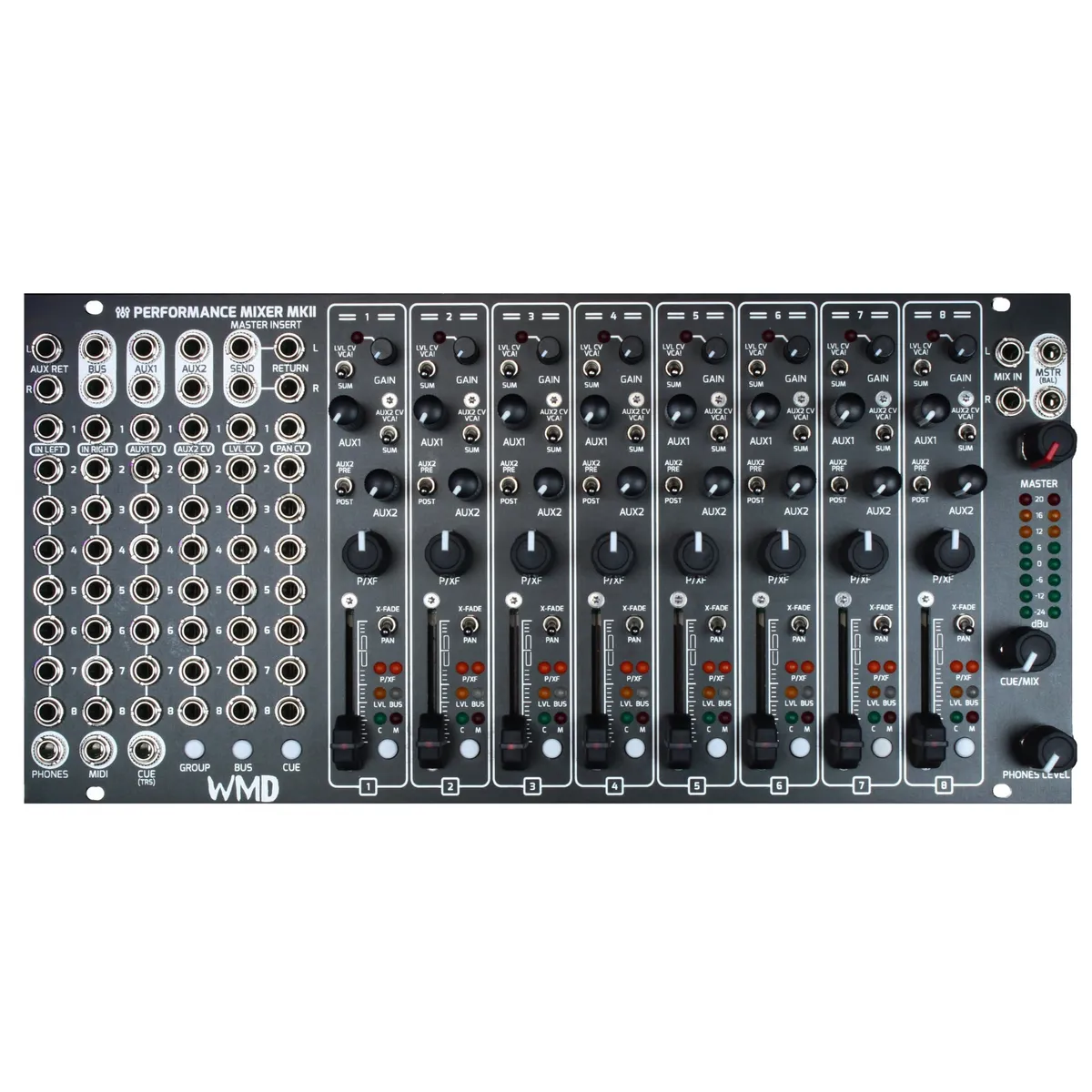
8-channel stereo Eurorack performance mixer
1Introduction
The Performance Mixer MKII is an eight-channel stereo Eurorack mixer designed for live performance and the studio. Each channel offers stereo or dual-mono input, input gain, two auxiliary sends, panning or crossfading, a CV-controllable level fader, cueing, muting, and flexible bus routing. A master section provides a stereo insert, headphone monitoring, a DJ-style cue/mix control, and balanced master outputs. This manual also covers the companion PM Channels MKII expander and the PM MKII Returns, DB25 MKII, and Direct Outs accessory modules.
The MKII was conceived with field-replaceable parts in mind, so the faders and other wear components can be serviced without sending the heart of your rack back to WMD.
2Channel Inputs, Level & Panning
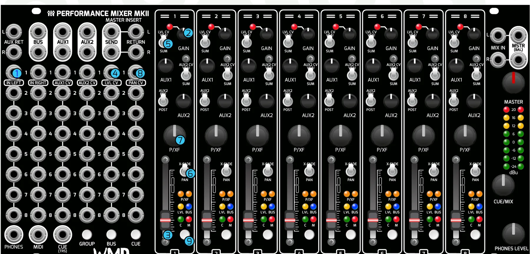
- Channel Inputs: Stereo or dual-mono audio inputs for the channels. Left normals to Right for mono signals. Can be switched to dual-mono operation (see the LVL CV switch and Pan/X-Fade switch).
- Gain Knobs: Input gain for the channel. Attenuation and boost from -12 dB to +20 dB. The clip LED lights just before the waveform begins to clip.
- Faders: Direct control over the channel's level.
- LVL CV Inputs: CV control over the channel level.
- LVL CV Switch: Direct control over how LVL CV and the fader interact. VCA! Mode (up) makes the fader require an input voltage on the LVL CV jack, and the fader attenuates that voltage. SUM Mode (down) sums the CV with the fader position — this should be your default position.
- Pan/X-Fade Switch: Sets the behavior of the P/XF knob. X-FADE crossfades between inputs one and two, both panned to center (only audible in post-fade outputs). PAN is traditional panning; left input normals to right so mono signals can be panned with the P/XF knob.
- P/XF Knob: Direct control over panning or crossfading for the channel. -3 dB centered pan law.
- Pan CV Inputs: Bipolar CV inputs for controlling Pan or X-Fade. Accepts -5 V to +5 V signals. The pan knob always sums with CV.
- Channel Button: Normally a MUTE toggle; the MUTE LED (M) lights red when a channel is muted. Hold CUE and press the channel button to toggle CUE send (the C LED lights green when cue is active). Hold BUS and press the channel button to change BUS routing (the BUS LED lights blue or purple to show bus status).
3Auxiliary Sends, Returns & Master Insert
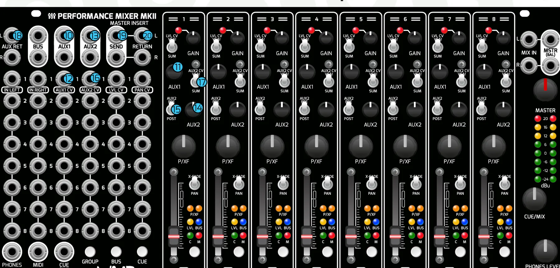
- Aux 1 Output: Stereo output for Auxiliary Send 1. Use these to send to mono or stereo effects. Aux 1 outputs are post-fader and post-pan only, so sound only comes out when the Aux 1 knob and the channel fader are turned up. Same fader curve as the LVL fader.
- Aux 1 Knob: Direct control over auxiliary send 1 level per channel.
- Aux 1 CV Inputs: CV control over auxiliary send 1 level. Aux 1 CV sums with the Aux 1 level knob.
- Aux 2 Outputs: Stereo outputs for auxiliary send 2. Use these to send to mono or stereo effects.
- Aux 2 Knob: Direct control over auxiliary send 2 level per channel.
- Aux 2 Pre/Post Switch: Sets Aux 2 to be sent pre- or post-fader. PRE sends the signal regardless of fader position (pre-pan / pre-crossfade). POST sends the signal only when the fader level is up (post-pan).
- Aux 2 CV Inputs: CV control over auxiliary send 2 level.
- Aux 2 CV VCA!/SUM Switch: Sets the CV behavior of Aux 2. VCA! (up) makes Aux 2 require an input voltage on the CV jack, which the Aux 2 knob attenuates. SUM (down) sums the CV with the Aux 2 knob position — this should be your default. Same fader curve as the LVL fader.
- Aux Return Inputs: Stereo unity-gain inputs that sum directly to the master outputs. Use these to return a stereo effect signal. Left input is normalled to right for mono return signals.
- Master Insert Send: Stereo outputs for adding effects to the master bus, e.g. a stereo filter, compressor or EQ.
- Master Insert Return: Unity-gain inputs for the master insert. Replaces the signal on the master outputs.
4Phones, Cue, Mix In, Master & MIDI
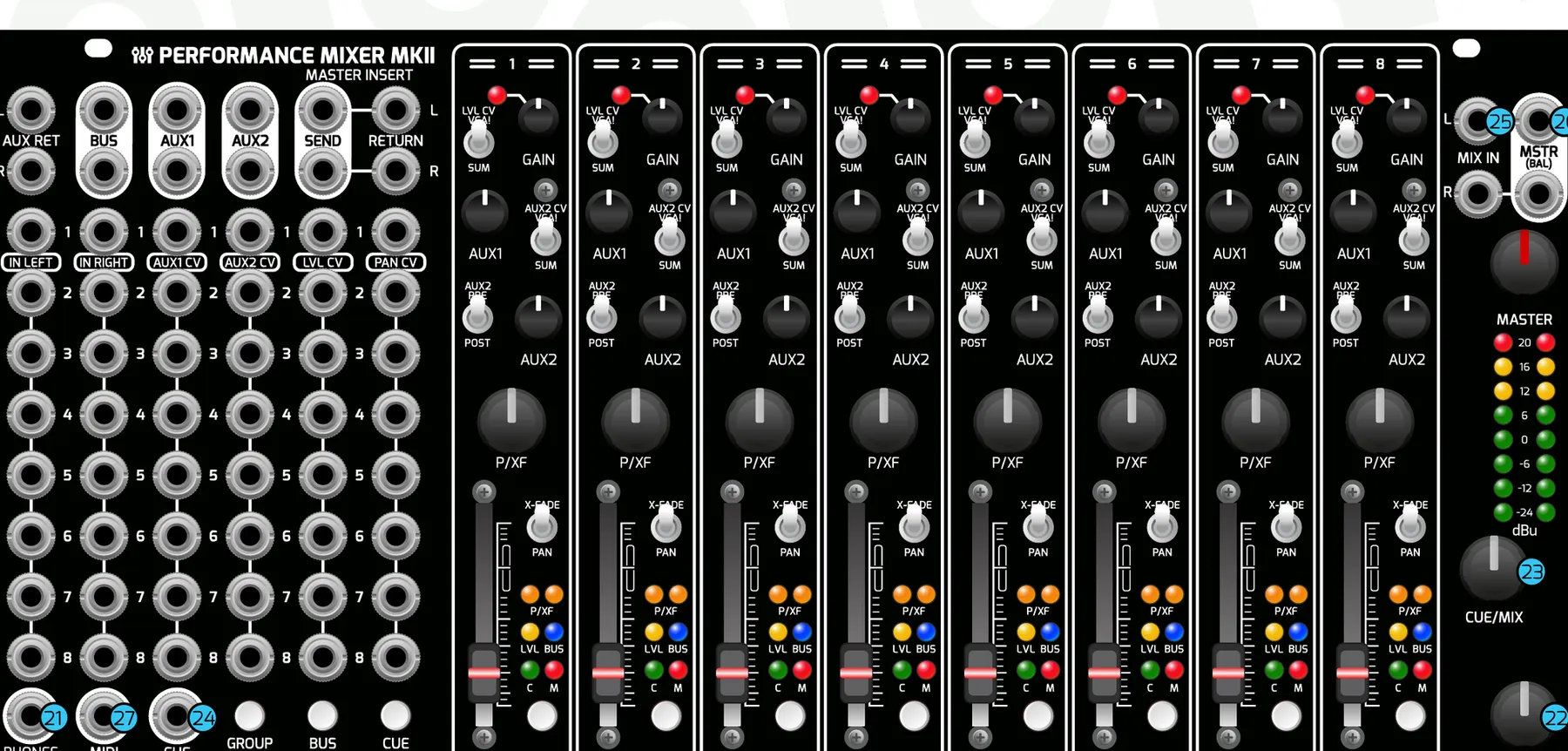
- Phones Output: Stereo TRS output for monitoring with headphones.
- Phones Level Knob: Attenuator for the headphone amplifier. The headphone amplifier can get very loud — take care when monitoring with headphones!
- Cue/Mix Knob: DJ-style cue mixing. Cue is always pre-fader and pre-pan/crossfade. CUE/MIX to the left listens to the stereo cue bus; to the right listens to the main mix.
- Cue Output: TRS stereo output of the unity-gain sum of the cue bus. Tip is Left, Ring is Right. Can be used as yet another stereo send track.
- Mix Inputs: Stereo return that bypasses the master insert and sums directly to the master output. Can be used as a second stereo aux return, but it will bypass the master insert. Great for collaboration, chaining two mixers together, or adding a stereo sub-mix.
- Master Outputs: Balanced TRS outputs, attenuated by the master level knob. Use these to go directly into front-of-house for a live set, your audio interface for recording, or powered speakers for monitoring. TS cables are okay, but TRS-to-TRS or TRS-to-XLR is preferred to minimize noise and interference.
- MIDI Output: Requires a Type-A MIDI 3.5 mm to DIN connector (available on WMDevices.com). See the MIDI Guide for more info.
5Mixer Settings
Hold GROUP + BUS + CUE together and press a numbered channel button to access each setting, as shown below.
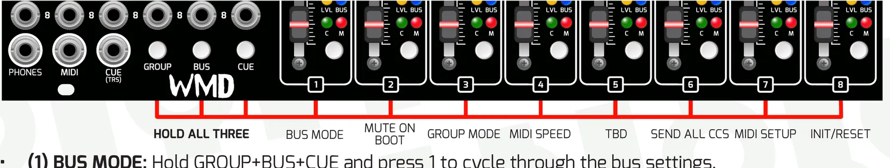
5.1Bus Mode (Channel 1)
Hold GROUP + BUS + CUE and press channel 1 to cycle through the bus settings:
BLUE — Parallel processing (default). Holding BUS and pressing a channel button lights the bus LED blue and sends that signal to the bus as well as the master outputs.
PURPLE — Submix processing. Holding BUS and pressing a channel button lights the bus LED purple and removes that signal from the master outputs, sending it only to the bus outputs. Return it via a channel, the FX return, or the MIX inputs to hear it.
RED — Tri-State Mode. Holding BUS and pressing a channel button cycles through Blue, Purple, then off.
5.2Other Settings
Mute on Boot (Channel 2) — Enable or disable mute configuration on power-up. When disabled, all channels unmute on power-up (channel 1 flashes; default). When enabled, the last saved mute configuration loads on power-up (channel 2 flashes).
Group Mode (Channel 3) — Change the group recall mode. Combo Mode (channel 1 flashes): hold GROUP and select multiple MUTE, BUS, and/or CUE selections; action on release. Group Recall Mode (channel 2 flashes; default): hold GROUP and push a channel button to recall a MUTE/CUE/BUS state; action on release. Recalling a group overrides the current Bus Mode setting but does not change the setting.
MIDI Transmit Rate (Channel 4) — Shows 3 green flashes on CH1–CH5. CH1 is fastest, CH5 is slowest.
Cue/Mute Default (Channel 5) — Sets the default button press to MUTE (default) or CUE.
Send All CCs (Channel 6) — Sends the current state of all MIDI CCs at once, including any connected Channels modules. CCs must be enabled.
MIDI Setup (Channel 7) — Enters the menu for setting up the transmitting MIDI channel (see the MIDI Guide).
Init/Reset (Channel 8) — Initialize the mixer to factory settings. First press flashes a warning. Second press resets everything to factory (default) settings. Third press initializes all saved groups and clears eeprom memory.
5.3Group Recall Mode Explained
First, set up the mute, bus, and cue configuration you want to save. Next, hold GROUP + CUE and press a channel button (1–8) to save that configuration to that slot. Finally, use the GROUP button plus a channel button (1–8) to recall a group's settings. Action is on release of the channel button.
6MIDI Guide
The Performance Mixer MKII includes a MIDI output so you can use it as a MIDI controller for your DAW, digital recorder, or other gear that accepts MIDI input. The intention is to capture an overlay of the mixer control layer in real time so it can be combined with the raw audio in your DAW to recreate a performance, letting you move to post-production more quickly.
We recommend recording PRE-FADER outputs via DB25 or Direct Outs. Pre-fader recording captures each channel without fader, mute, or panning moves — a raw recording at the input (post-gain, post-insert). With the MIDI output, you can record those pre-fader tracks and use MIDI CCs mapped to DAW parameters to capture your fader and knob movements as MIDI automation during a performance, making editing easier while keeping the original recordings intact.
MIDI outputs CCs for the LVL fader (including mute actions), PAN, AUX1 and AUX2. The best way to map the controls to your DAW is to use MIDI learn — for example, map faders 1–8 to faders in your DAW, the panning knob to the DAW pan, and the same for both sends.
6.1MIDI Setup
To enter MIDI setup, hold GROUP + BUS + CUE and press channel 7.
MIDI Channel — Press any channel button to select channel 1–8; press again for 9–16 (default channel is 1). The BUS LED shows blue for MIDI channels 1–8 and red for 9–16.
CC Enable — While in MIDI setup, the three left buttons correspond to the CV jacks above them. Hold one of these buttons and press a channel button to enable/disable the corresponding CC on that channel (default is all enabled).
GROUP = AUX 1 / 2 CC — LED shows blue for Aux 1 only enabled, red for Aux 2 enabled, purple for Aux 1 & 2 enabled, off for both disabled.
BUS = LVL CC — LED shows blue for LVL enabled, off for LVL disabled.
CUE = PAN CC — LED shows blue for PAN enabled, off for PAN disabled.
Exit MIDI Setup — Hold all 3 control buttons and press any channel button.
6.2MIDI Implementation
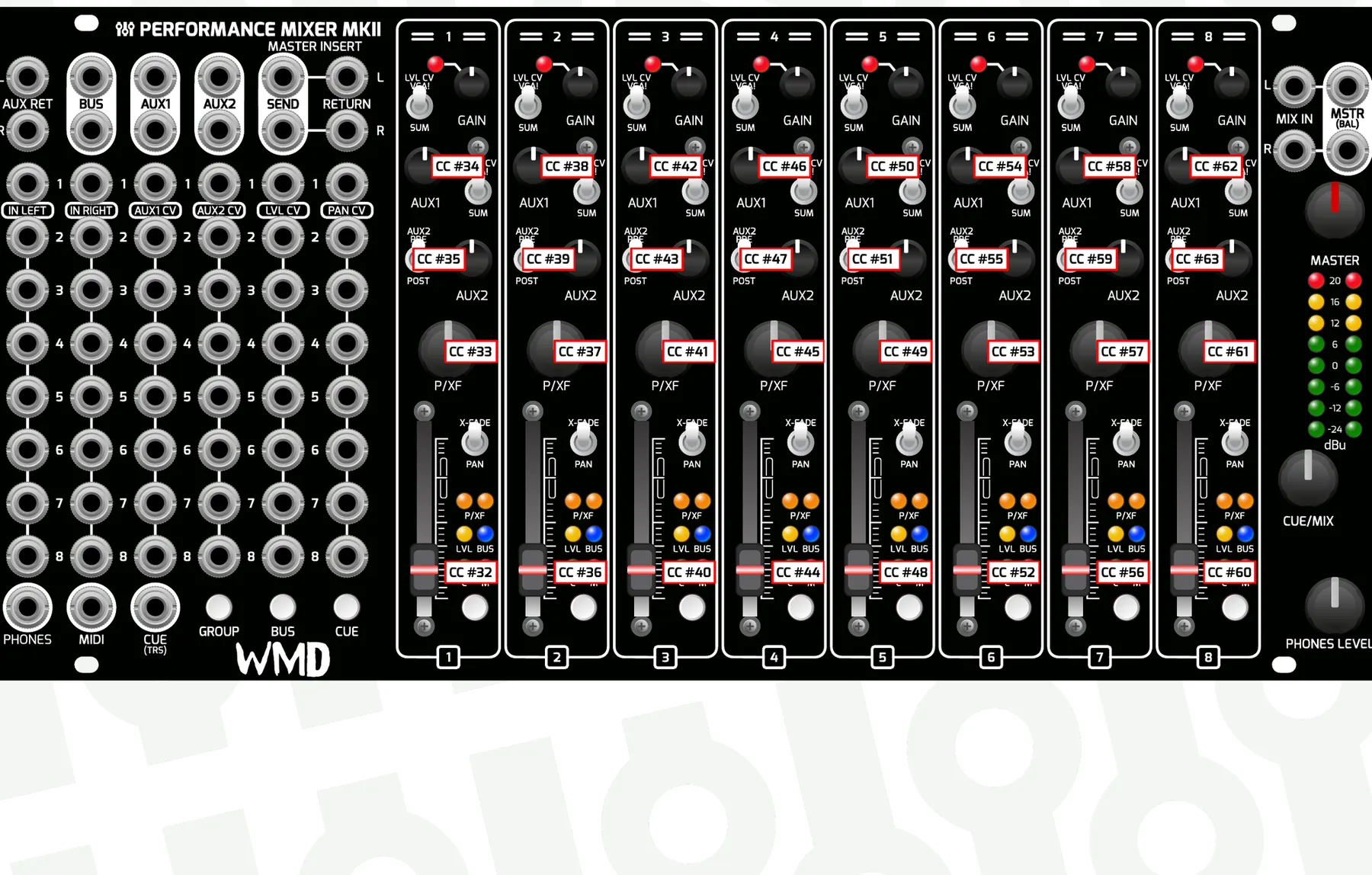
The first MIDI CC number is 32, and CCs are arranged by channel strip.
| Control | Ch 1 | Ch 2 | Ch 3 | Ch 4 | Ch 5 | Ch 6 | Ch 7 | Ch 8 |
|---|---|---|---|---|---|---|---|---|
| Level | 32 (20) | 36 (24) | 40 (28) | 44 (2C) | 48 (30) | 52 (34) | 56 (38) | 60 (3C) |
| Pan | 33 (21) | 37 (25) | 41 (29) | 45 (2D) | 49 (31) | 53 (35) | 57 (39) | 61 (3D) |
| Aux 1 | 34 (22) | 38 (26) | 42 (2A) | 46 (2E) | 50 (32) | 54 (36) | 58 (3A) | 62 (3E) |
| Aux 2 | 35 (23) | 39 (27) | 43 (2B) | 47 (2F) | 51 (33) | 55 (37) | 59 (3B) | 63 (3F) |
MIDI CC numbers per channel strip (decimal, hex in parentheses).
7Rear Connections
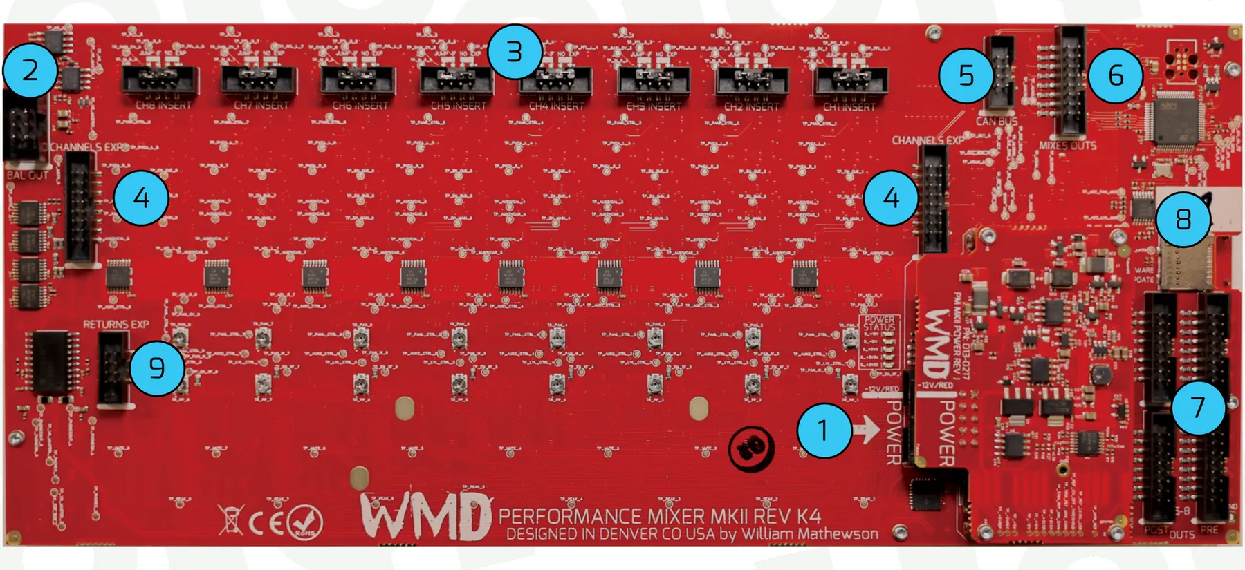
- Power Header: 2x5-pin horizontal Eurorack power header. Shrouded and reverse-polarity protected. Do not lift or handle the mixer by the power board.
- Balanced Out: 6-pin balanced output header for connection to Intellijel case outputs.
- Channel Insert Headers: 8x 8-pin, 2 mm pitch headers for connection to WMD insert modules (future).
- Channels EXP: Two 2x8-pin 2 mm headers for connecting PM Channels MKII to the PM MKII. Use one, the other, or both headers to add up to 4 expanders. PM MKIIs cannot be chained together.
- CAN Bus: Currently unused for customer-facing needs. Do not connect anything to this.
- DB25 Mixes: 2x8 2 mm header for stereo mixes of the MASTER, AUX 1, AUX 2, and BUS send signals.
- DB25 Outputs: 4x 2x8-pin 2 mm headers for connection to the PM DB25 MKII or Direct Outputs expander. Pre-fader headers carry direct outs that are post-gain, post-insert (no LVL or PAN/XF movement/CV). Post-fader headers carry all LVL and PAN/XF movement and CV.
- Memory Card Slot: Memory cards are used for loading new firmware only and must be removed during normal use.
- Returns EXP: 2x4-pin 2 mm headers for connection to the PM Returns expander module.
8Firmware Updates
The PM MKII and Channels MKII both use the same firmware file and can be updated with the same memory card (one at a time). Firmware must be the same revision on connected PM MKII and Channels MKII units.
Memory Card Information:
The memory card MUST be a SanDisk SDHC type, 8–32 GB. No other brands or types are supported.
Cards are available on wmdevices.com if you do not own a SanDisk SDHC card.
Tested cards: SanDisk SDSDQAB-008G (WMD Metron card), SDSDQAF3-008G-I, SDSDQ-032G-C4, and SDSQQNR-032G-GN6IA.
8.1Update Procedure
Set up the card:
Format the card for FAT32.
Download the firmware from the Performance Mixer MKII product page; updates are near the top of the page.
Copy the downloaded firmware file “PM_MKII.bin” onto the memory card in the root directory.
Prepare the module (it can stay connected and in the rack):
Power off the PM MKII / Channels MKII.
Remove all four screws and lift the left side of the module. You do not need to unpatch unless cable interference prevents lifting it.
Insert the memory card into the slot on the left side of the module, at the rear of the board.
Power the unit on. LEDs are briefly red while it reads the card (if they stay red, there is a problem with the card or firmware). Green LEDs indicate everything is OK and the flash is being prepared. Blue LEDs flash for about 10–20 seconds while writing the firmware. The module then goes all green and boots. The unit may initialize settings and/or group recall settings when updating to a new save revision.
Last step: remove the memory card from the module, then reinstall the screws.
8.2Troubleshooting
If your mixer is not working and is displaying solid red lights on channels 1–4, you are in an error state. Some mixers will also show a blinking LED on channel 8 to indicate you are in an error state. Channels 1–4 indicate the error code.
Find the matching pattern in the table below. In the Display column the four dots are the channel 1–4 MUTE LEDs from left to right; a filled dot is a lit LED.
| Error | Display (Ch 1–4) | Solution |
|---|---|---|
| No memory card | Insert a supported SanDisk SDHC card (8–32 GB) with PM_MKII.bin in the card's root folder, then power-cycle. | |
| Card not readable | Reformat the card as FAT32 and re-copy PM_MKII.bin. Only SanDisk SDHC cards (8–32 GB) are supported. | |
| Firmware file not found | Copy PM_MKII.bin to the top (root) level of the card, not inside a folder, named exactly PM_MKII.bin. | |
| Firmware file wrong size | The file is incomplete or the wrong one. Re-download the PM MKII firmware and re-copy it to the card. | |
| Firmware file not recognized | Re-download the official PM MKII firmware and don't rename or edit it. The mixer will not start until a valid file is present. | |
| Update interrupted | Leave the card inserted and power-cycle to restart the update. Never remove the card or cut power during an update. | |
| Internal error | Remove the card and power-cycle. If the error returns immediately, contact WMD support. |
Error codes shown on the channel MUTE LEDs.
9PM Channels MKII Expander
PM Channels MKII adds four more channel strips to your Performance Mixer MKII. Up to 4 Channels MKII can be connected to a single PM MKII. Each Channels MKII must be independently connected to power, and connections from unit to unit are made via 2.0 mm ribbon cables (180 mm standard length; longer cables are available on wmdevices.com).
Each Channels MKII channel strip is a copy of the strips on the PM MKII — see the channel controls described above for detail.
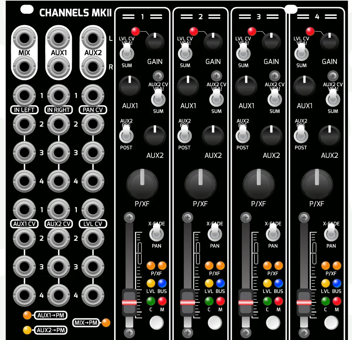
9.1Standalone Operation
The Channels MKII module can be used standalone as a 4-channel mixer with a few less features than the standard PM MKII. In standalone operation, the channel buttons operate only as mutes. The MIX outputs always mix the faders on the Channels MKII (they will not mix inputs from other units), and the AUX outputs always mix the AUX1 and AUX2 bus on the Channels MKII (no connected units mix to these outputs).
9.2Output Settings
When connected to the PM MKII, the MIX, AUX1, and AUX2 outputs on the Channels MKII can function independently of the Performance Mixer MKII, allowing you to use it as a standalone sub-mixer, an extension of the PM MKII, or a combination of both. These settings can be saved and loaded with Group Recall.
To configure these settings, hold GROUP, BUS, and CUE on the PM MKII and then press a channel button on the Channels expander. The LEDs on the bottom left of the Channels MKII indicate the status of the MIX, AUX 1, and AUX 2 routings to the PM MKII; an LED is lit if the signal is routed to the corresponding output on the PM MKII.
MIX → PM (1) — Toggles MIX from the MIX output on the PM MKII.
AUX1 → PM (2) — Toggles AUX 1 on/off to the AUX 1 output on the PM MKII.
AUX2 → PM (3) — Toggles AUX 2 on/off to the AUX 2 output on the PM MKII.
Routing → PM Group Recall (4) — Enabled (default): when a group recall is initiated on the PM MKII, the MIX, AUX1, AUX2 → PM settings are saved and recalled with that group (the three LEDs flash 6 times when changing to Enabled). Disabled: MIX, AUX1, AUX2 → PM routing is always manual and only changes by directly changing the settings. Each Channels MKII has its own setting for this; multiple units are independent.
9.3Connecting Channels MKII
Connect Channels MKII to power with the included standard-pitch 10-pin ribbon cable.
Connect Channels MKII to the PM MKII with the included 16-pin 2 mm ribbon cable. Use whichever header fits your case configuration best. To connect multiple Channels MKII to one PM MKII, daisy-chain them together using the multiple header connections on the Channels MKII, or use the two headers on the PM MKII. Standard cable length is 180 mm; 400 mm and 800 mm cables are available from wmdevices.com.
MIDDLE / END switch: if you are putting a Channels MKII in the middle of the chain, set this switch to MIDDLE. If a Channels is at the end of the chain, set it to END. If a PM MKII is in the middle of 2x Channels MKII modules, both Channels should be set to END.
Secure the modules to your Eurorack case's rails with the included screws.
9.4Channels MKII Firmware & MIDI Setup
Firmware must be the same revision on both the PM MKII and Channels MKII, and must be updated via memory card (see Firmware Updates above). If firmware does not match and the units are connected, the Channels MKII will slowly double-blink channel 1's Mute LED and its interface will be halted.
Each Channels MKII needs to be assigned its unit number for MIDI. Enter MIDI SETUP mode (GROUP + BUS + CUE & CH7 on the PM MKII), then press a channel button on the Channels MKII to assign it to unit 1–4. This offsets the MIDI CCs so each Channels has a unique set of CCs (default is 1).
10Expanders & Accessories
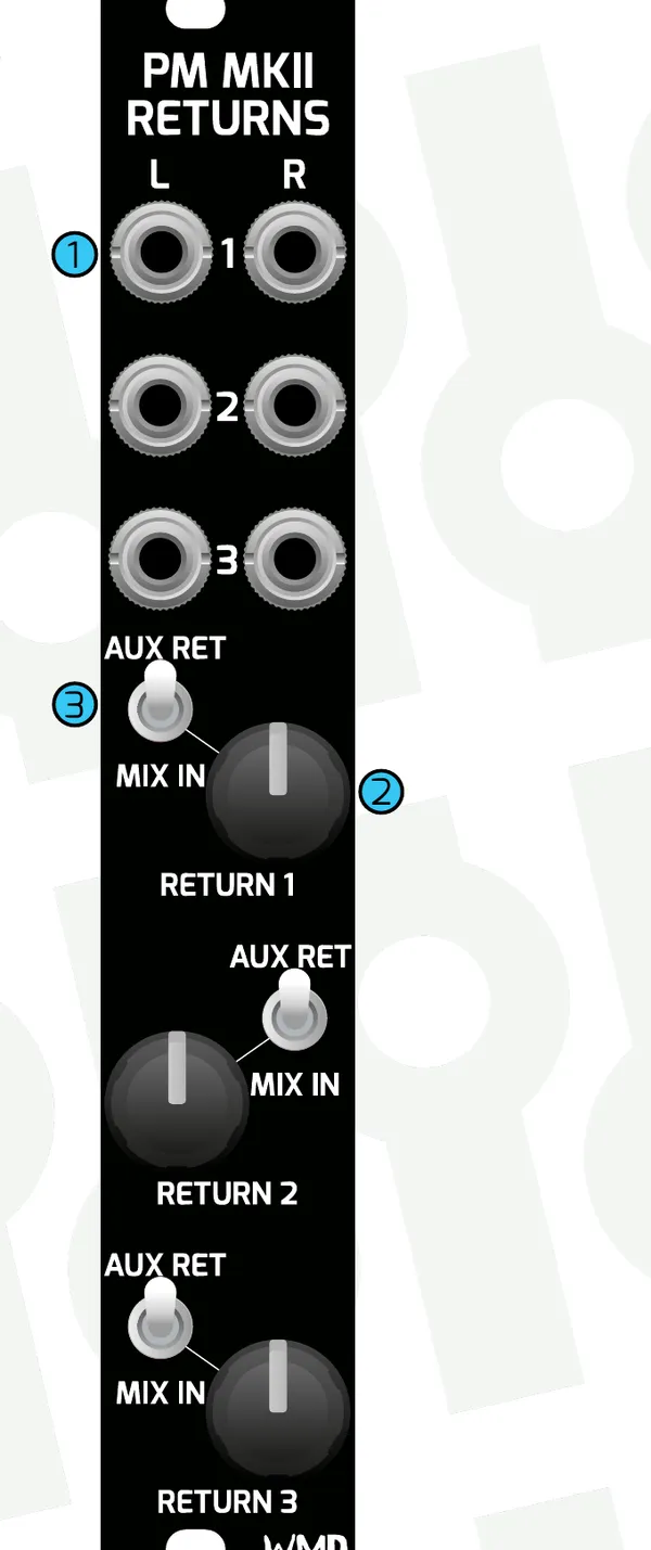
10.1PM MKII Returns
PM MKII Returns adds 3 stereo returns to your Performance Mixer MKII or Channels MKII.
Stereo Inputs — 3x stereo inputs. Left is normalled to right for mono signals.
Return Levels — These function in standalone mode as well as when connected to the main mixer.
Routing Switch — Changes where signals are routed. AUX RETURN routes the signal to the aux return bus, which is pre-master-insert (affected by the master input). MIX IN routes the signal into the MIX BUS, which is post-master-insert (bypasses the master insert and is not affected).
To connect: attach the Returns module to the headers on the rear of the PM MKII or Channels MKII using the included 300 mm 2 mm 2x4 ribbon cable. Returns does not require power. Secure the module to your case's rails.
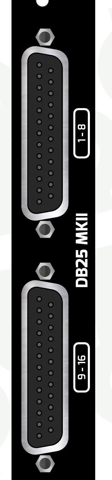
10.2DB25 MKII
DB25 MKII provides individual balanced outputs for each channel on the PM MKII and Channels MKII. To capture all 16 outputs simultaneously, connect 2x DB25 cables into a 16-channel audio interface or recorder. Though the connection looks digital, these outputs are 100% analogue and use the TASCAM DB25 standard.
Pre-Fader Connection — Outputs the signal post-gain, pre-pan, pre-fader. Best for multitrack recording, as pan and fader moves will not be included in the audio.
Post-Fader Connection — Outputs the signal post-fader, keeping all pan and fader moves intact. Use if you want to include pan and fader moves, or any CV connected to panning or level.
Mixes Connection — The MSTR, BUS, AUX1, and AUX2 stereo mixes are also available on this header. You may want to record these via DB25.
Any of the above connections can be mixed and matched on a DB25 MKII — document what's connected where for your own sanity. To connect: power the DB25 MKII with the included standard-pitch 10-pin ribbon cable, then connect the PM MKII OUTS to the rear headers using the included 2 mm pitch 16-pin cables (standard 400 mm; 800 mm available). There are pre- and post-fader header sets on both the PM MKII and Channels MKII — 2x ribbon cables for the PM MKII, 1x for a single Channels MKII.
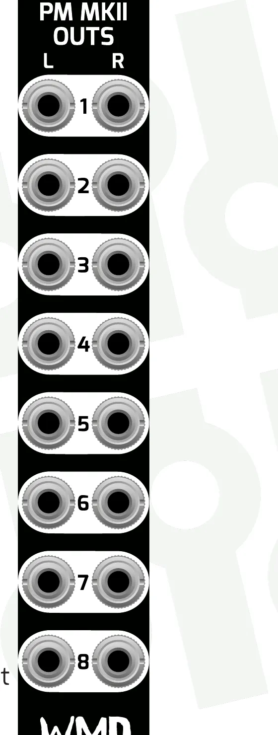
10.3PM MKII Direct Outs
PM MKII Direct Outs provides 8 pairs of unbalanced outputs for the Performance Mixer MKII.
Pre-Fader Connection — Outputs the signal post-gain, pre-pan, pre-fader. Best for multitrack recording (pan and fader moves are not recorded).
Post-Fader Connection — Outputs the signal post-fader, keeping all pan and fader moves intact. Best for using the mixer as a bank of VCAs.
These outputs are unbalanced and not attenuated — best for use with other Eurorack modules. If using to record or interface with a computer, a Eurorack audio interface is recommended. No power is required. Connect to the rear headers of the PM MKII or Channels MKII using the included 2 mm pitch 16-pin cables (standard 400 mm; 800 mm available). There are pre- and post-fader header sets — 2x ribbon cables for the PM MKII, 1x for a single Channels expander. Secure the module to your case's rails.
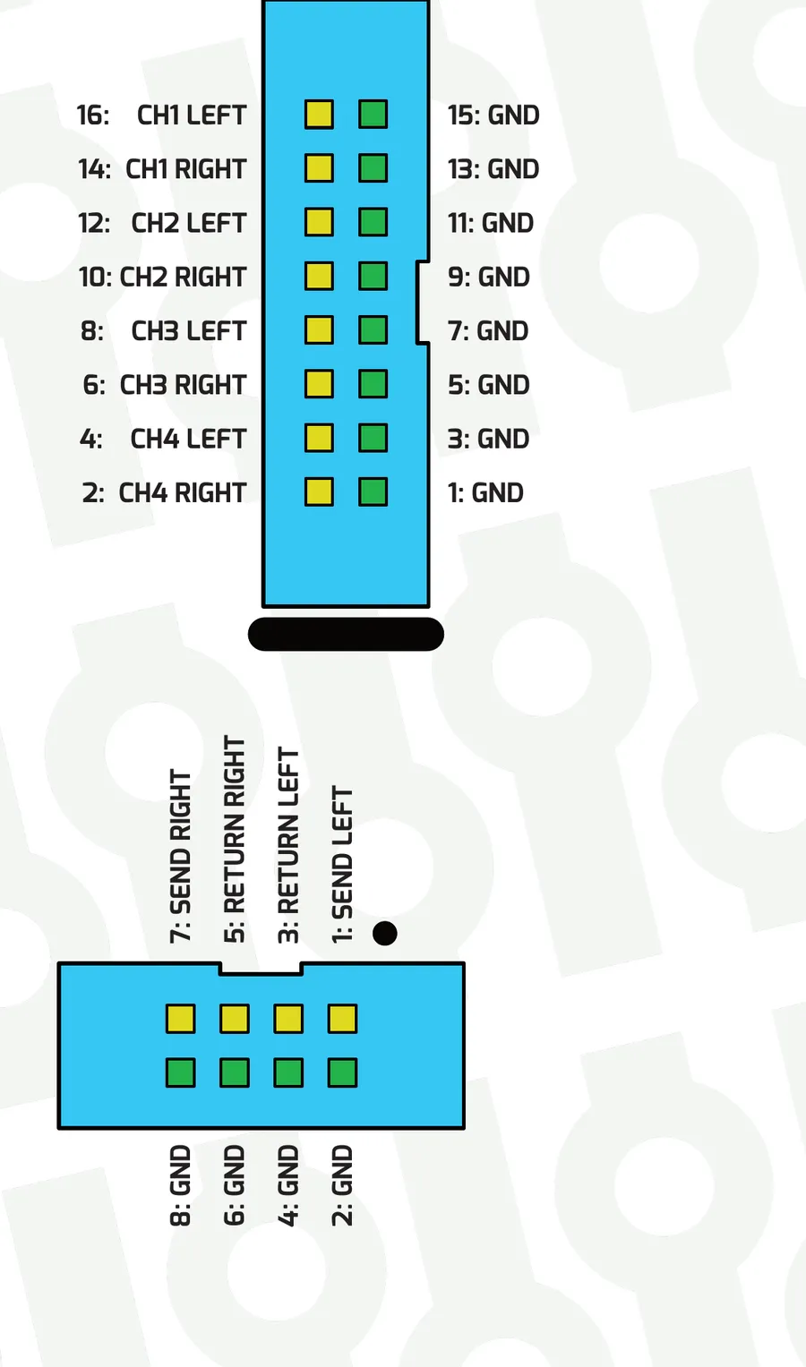
11Header Signal Definitions
Outs Headers provide pre-fader and post-fader signals for external processing or recording on a 2 mm pitch, 16-conductor header. Every odd pin is connected to ground to preserve signal integrity on the ribbon cable; even pins contain signal. Each header contains four stereo channels (8 total signals).
Insert Headers provide a post-gain, pre-fader insert point for additional processing on a 2 mm pitch, 8-conductor header. Every even pin is connected to ground; odd pins contain signal. When not used, pins 1–3 and 5–7 must have jumper sockets installed so signals flow through to the channel. Levels are Eurorack level. Send pins (1 Left, 7 Right) are outputs going to the next piece of gear; return pins (3 Left, 5 Right) are inputs going to the rest of the PM MKII internally. The signals on the returns drive the pre-fader parts of the mixer (CUE bus, PRE-OUTS, and AUX2 PRE).
12Specifications
12.1Performance Mixer MKII
Dimensions:
- Width: 52HP
- Depth: 36mm behind panel including cables
- Board height between rails: 111.5mm
Power:
- +620mA, -560mA
- Uses up to +/-750mA if channels or busses are distorted.
Inputs:
- Channel inputs: 20kΩ impedance
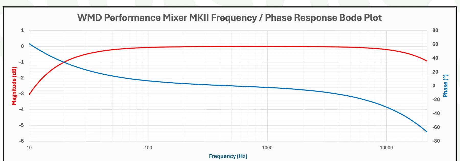
- Channel input HPF: -3dB @ 10Hz
- Channel input gain: -12dB to +20dB
- Fader/Aux gain: -100dB to +5dB
- Level/Aux CV: 0 to 5V, 100kΩ impedance
- Pan CV: -5 to +5V, 200kΩ impedance
Outputs:
- Master output: Balanced 3.5mm TRS @ 600Ω nominal, DRV135 drivers
- Master level: Full level = modular level; attenuate to your optimal level with the MSTR knob.
- All other outputs: 1kΩ modular level
- Pan curve: -100dB / 0dB at hard pan, -3dB / -3dB at center
Audio Performance:
- Frequency response: +/-0.5dB 20Hz - 20kHz
- Left/right coherence: Better than +/-0.5dB
- Phase: All inputs, outputs and headers are phase correct.
12.2PM Channels MKII
Dimensions:
- Width: 24HP
- Depth: 36mm behind panel including cables
- Board height between rails: 111.5mm
Power:
- +320mA, -280mA
- Uses up to +/-350mA if channels/mix/auxes are distorted.
Inputs:
- Channel inputs: 20kΩ impedance
- Channel input HPF: -3dB @ 10Hz
- Channel input gain: -12dB to +20dB
- Fader/Aux gain: -100dB to +5dB
- Level/Aux CV: 0 to 5V, 100kΩ impedance
- Pan CV: -5 to +5V, 200kΩ impedance
Outputs:
- Outputs: 1kΩ modular level
- Pan curve: -100dB / 0dB at hard pan, -3dB / -3dB at center
Audio Performance:
- Frequency response: +/-0.5dB 20Hz - 20kHz
- Left/right coherence: Better than +/-0.5dB
- Phase: All inputs, outputs and headers are phase correct.
12.3PM Returns, DB25 & Direct Outs
PM Returns:
- Width: 4HP
- Depth: 24mm behind panel including cables
- Connectivity: 1x 8p 2.0mm ribbon cable
- Power: +/-0mA (no power connection)
- Input impedance: 10kΩ
DB25 MKII:
- Width: 4HP
- Depth: 48mm
- Power: +12V = 150mA, -12V = 150mA
- Output impedance: 600Ω balanced
- Output drivers: 16x TI DRV135
- THD+N: <0.1%
- Nominal output level: +4dBu
- PM MKI adapter board (for connection to the original Performance Mixer): consumes +/-25mA
Direct Outs:
- Width: 4HP
- Depth: 24mm behind panel including cables
- Connectivity: 2x 16-pin 2mm ribbon cables
- Power: +/-0mA (no power connection)
- Output impedance: 1kΩ
13Resources
Visit the Performance Mixer MKII product page for firmware downloads, cables and accessories, and the Multitrack Recording Guide.