METRON
Advanced Trigger and Gate Sequencer
Supporting Firmware V1.75+
1Introduction
Thank you for choosing the WMD Metron Performance Sequencer. Metron is a dynamic performance gate sequencer ideal for real-time pattern creation, live performance, and improvisation. It features 16 outputs and over 93 buttons, making it easy to "push" the rhythm and control of your Eurorack into rewarding territories. To make the most of the machine, we recommend that you carefully read this manual.
A Note From the Designer
WMD's niche is: "New Sounds, Maximum Experience", and while Metron may be silent on its own (unless you really like clicks), it absolutely creates the maximum experience one can have with modular and rhythm. We have been pushing our gear to be ever more playable and versatile in a live setting, to help you play for longer, make better transitions, and get the most out of the other modules in your rig. We make gear to make your mind's ear a reality.
Years of internal iteration of Metron gives you modern, unequivocal control over timed events while retaining the familiarity of the classic trigger sequencer. We have agonized over all aspects of the human interface to create a device that allows the immediate expression of rhythm. Three years of development, sixteen hardware revisions, and thousands of hours coding have resulted in a machine that is both fluidly satisfying to play and vast enough to challenge and excite its human for years.
Thank you for supporting WMD, you allow us to continue to create. We hope to do the same for you.
1.1Conventions of This Manual
We have used the following conventions throughout the manual:
Button names are written in uppercase and bracketed letters. For instance, the button labeled "DUPL" is called [DUPL]. Encoder 1 would be referred to as ENCODER 1, while the encoder 1 button will be [ENCODER 1]. A push of the encoder button will be indicated with brackets, while a turn of the encoder will not.
Mode names are capitalized followed by the word Mode. The Compose Mode is an example of this.
Functions where settings can be made or actions performed are written in upper case letters and underlined. For example: SAVE SESSION.
Messages visible on a screen are written in upper case letters and enclosed in apostrophes. Like this: 'ENABLE'
1.2Accessibility Documentation
Accessibility documentation for the Metron is generously provided by Ty Littlefield. His screen-reader-focused guides and resources complement this manual — many thanks to Ty for his support of the visually impaired Eurorack community.
2User Interface and Connections
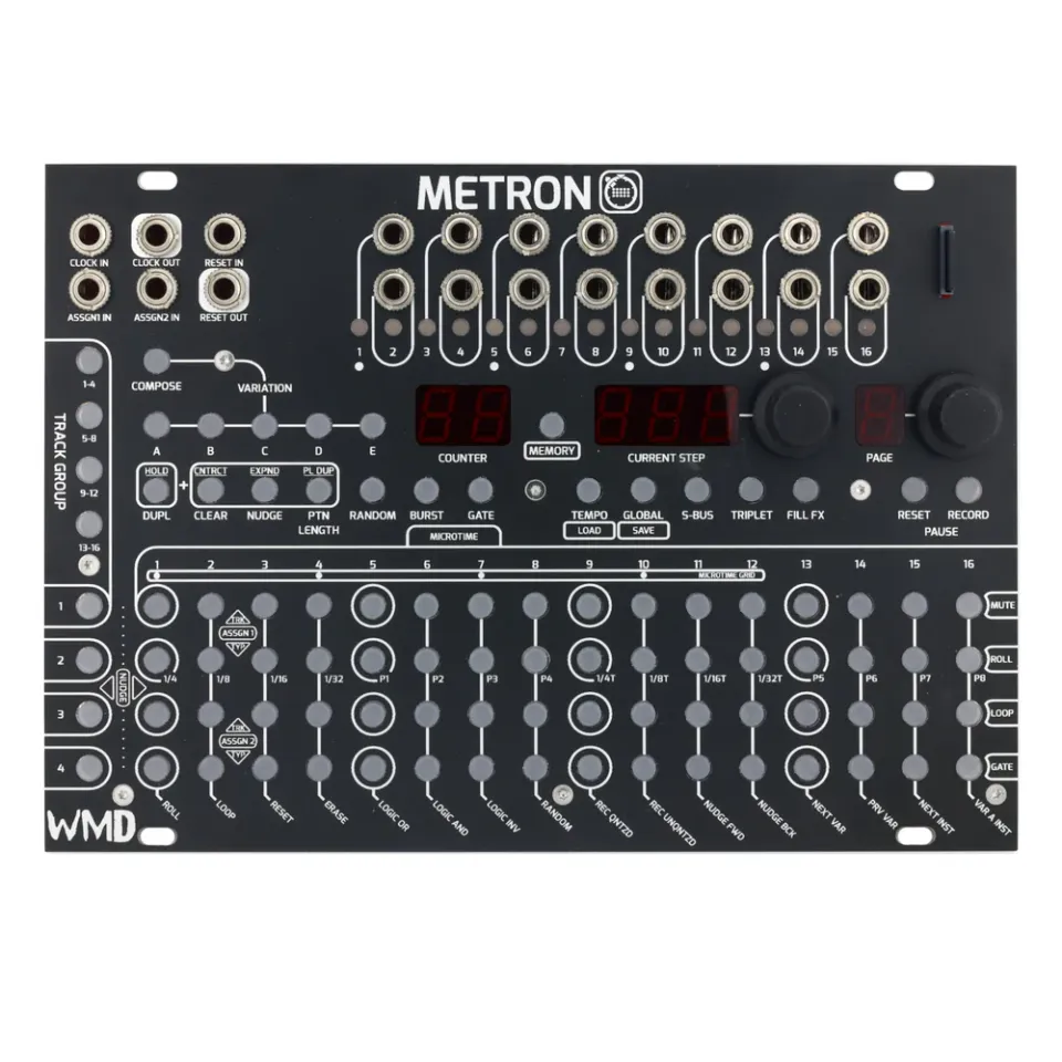
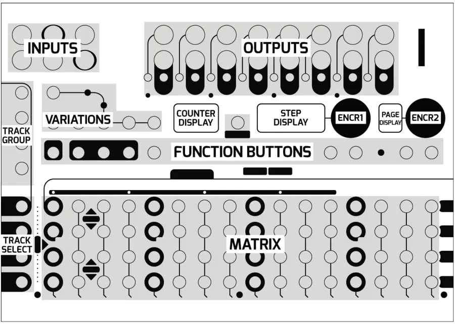
Metron's interface has been divided into functional sections. These sections will be referred to by the labels shown in the diagram below.
2.1Front Panel Overview
- VARIATIONS: There are 5 VARIATION buttons: A, B, C, D, and E, as well as the COMPOSE button. Use them to select and navigate between variations.
- TRACK GROUP: For most modes, Metron can display up to four tracks at a time. The group of tracks currently displayed are selected with the TRACK GROUP buttons.
- TRACK SELECT: Multifunction buttons generally associated with their corresponding track or MATRIX row function.
- FUNCTION BUTTONS: Allow the user to perform functions and enter the different modes on Metron.
- MATRIX: The main editing and data entry area of Metron. Its function changes depending on the current mode.
- COUNTER DISPLAY: Simple bar counting display that shows total time elapsed in the system. Various conditions will cause this counter to reset. Some modes will use this display for text information.
- STEP DISPLAY: Normally displays the master track playhead position of the playing variation. Some modes will use this to display text information.
- PAGE DISPLAY: Displays the page you are viewing. There are 16 pages but only a 1 digit display, so pages 9 — 16 are marked 1. — 8. with a decimal.
- ENCODER 1: Responds to push as well as turn. Its function is related to the current mode.
- ENCODER 2: Responds to push as well as turn. Its function is related to the current mode.
- MEMORY CARD: Metron requires a memory card for all memory functions. The unit will operate without a memory card, but nothing will save.
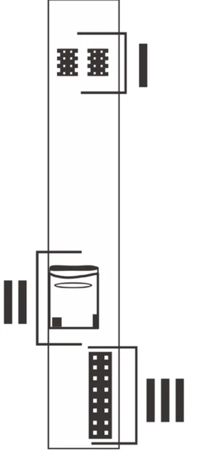
2.2Rear Connections
- POWER: Metron uses a 16 pin power connector in order to interface with the Select Bus. No power is consumed from the +5V or -12V rails.
- SYNCBUS: This connector allows for integration with modules and hardware that uses the SyncBus start/stop protocol.
- EXP: 2x proprietary bus connectors for connecting Metron and expansion units. One connector has a terminator labeled "EXP TERM."
- USB: Development use only. Not for use by customer.
- BOOT SWITCH: Enables the USB for recovery. Must be set to "NORM" for Metron to operate.
3Overview of Metron's Structure
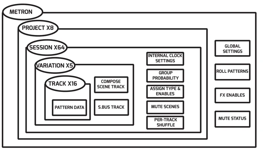
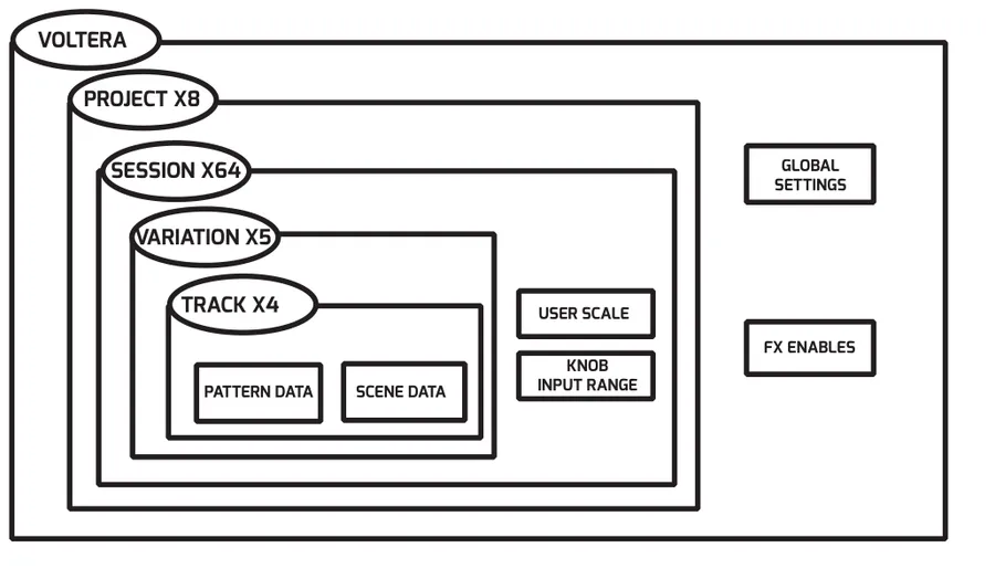
The following diagram shows Metron's memory hierarchy.
3.1Settings File
All data aside from project data is stored in the global settings file, called "SETTINGS.WMD", located at the root of the memory card.
You can view and edit a SETTINGS.WMD file from your browser — no need to boot the hardware. The web settings editor loads a settings file (or factory defaults), lets you change every user-editable field with validation, and downloads the re-serialized binary to copy back onto the memory card.
3.2Project
The root of the memory card also contains a number of project folders. All session data is stored inside the project folders. Metron can store up to 8 projects.
3.3Session
A session represents a memory save in Metron. Every project contains 64 sessions. A session contains the pattern data for 5 variations, 16 Mute Scenes, and settings for Internal Clock, Assign Input and Per-Track Shuffle.
3.4Variation
Variations are Metron's working memory. Each variation stores all of the track information. This means the user has 5 quick access memory slots available to them at all times. Additionally, Metron has the ability to play and edit separate variations. This allows the user to build a fresh pattern while the last one is still playing. Variations are the key to dynamic, evolving performances and composition with Metron.
3.5Tracks
Metron features 16 standard tracks as well as an S.BUS track, compatible with Select Bus. Each of these tracks can be up to 256 steps in length. Standard tracks offer additional deep pattern editing features, like 48ppqn resolution, shuffle and triplets.
3.6Compose Scene Track
Pairing any number of Voltera expanders with Metron will unlock an additional track referred to as the "COMPOSE SCENE TRACK." This information is presented here because the data for this track is distributed between the memory cards in expander units and Metron itself. For a deeper explanation of this track and its features see "SPECIAL FUNCTIONS".
4Voltera Expander
This section contains information related to the separately available Voltera expansion module. Ignore this section if you do not have Voltera.
4.1Introduction
Expand your rhythmic control of gates to control voltage with the Voltera voltage expander. Every Voltera adds 4 bi-polar CV outputs presented as completely independent tracks. Add up to 16 Volteras to a Metron unit for a total of 64 control voltage tracks.
4.2Rear Connections
- EXP: 2x proprietary bus connectors for connecting multiple Metron and Volteras.
- MEMORY CARD: Voltera requires a memory card to be present at all times.
- POWER: Voltera uses a 16 pin power connector. No power is consumed from the +5V.
4.3Connecting Voltera and Metron
The EXP headers on the back of Metron and Voltera make it extremely simple to connect expanders to Metron. Simply connect one 8-pin ribbon cable, supplied with Voltera, to either of the two EXP headers on Metron. Be sure to orient the red stripe toward the white dot printed next to the "EXP" label. Connect additional Voltera's either to each other or to the second EXP header on Metron. Finally, place the EXP TERM covers on any open headers. It is generally best practice to string or chain Metron and Volteras one by one, and place EXP TERM covers at either end of the string.
4.4Front Panel Overview
Voltera's interface is an extension of Metron's front panel. Most of the Metron track functions can be performed on Voltera by substituting a press of the [TRACK SELECT] button for the "turn" gesture described in section 4.5. Functions are explained with more detail in their corresponding Metron sections.
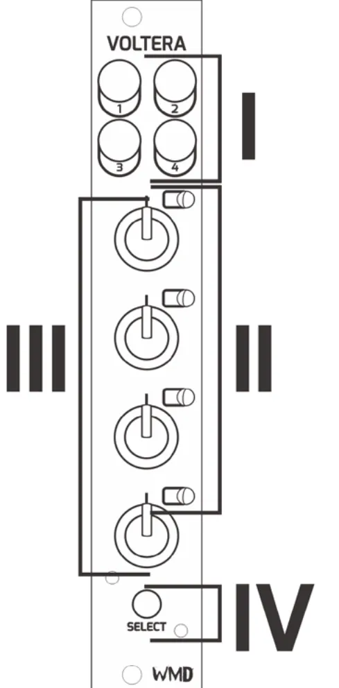
- OUTPUTS: 4x bi-polar CV outputs. Ranges from -5V to 5V.
- TRACK LED: 4x bi-color LED's associated with the track label.
- TRACK KNOB: 4x potentiometers for entering data and selecting tracks.
- SELECT BUTTON: Back lit momentary push button used for output takeover, and viewing set voltages.
4.5Track Select "Turn" Gesture

Because there are no individual track select buttons on the Voltera unit, the knobs are used to select each track using the "turn" gesture.
Perform the "turn" gesture by turning a knob to the full CW position then a small turn back in the CCW position.
Most functions that are available to Metron tracks are also available to Voltera tracks by using the "turn" gesture.
4.6Memory Overview
Voltera features its own memory card located on the rear of the unit for saving. The following section describes the file structure and layout of said memory card.
For more information on Voltera Operation, check out section 5.3 Voltera Basic Operations.
5Basic Functions
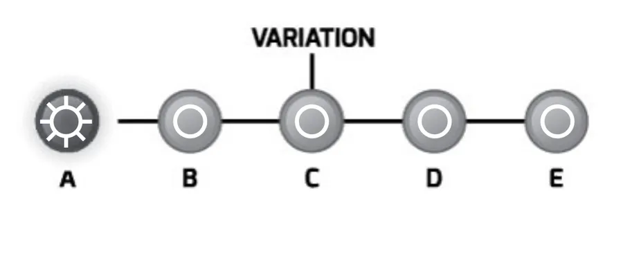
5.1Variations
Variations are key to making music with Metron. A variation contains the data for all 16 tracks. The user has 5 variations to facilitate pattern composition, allowing for seamless transitions when recording or performing live.
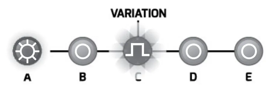
5.1.1Editing / Playing Variation
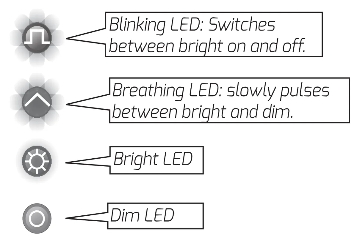
The user has the ability to view and edit variations that are not playing. The variation currently playing is indicated by a bright LED on the VARIATION buttons. If the editing variation is not the playing variation it will be indicated by a breathing LED on the VARIATION buttons.
5.1.2Select a Variation for Editing
To select a variation for editing simply press the [VARIATION]. To select a variation to play, see FOLLOW below.
5.1.3Follow
Variations can be triggered to follow one another. All playheads will reset once the new variation begins playing unless otherwise noted.
End of Variation: Press the [VARIATION] you would like to play once to edit, and a second time to follow at the end of the variation.
End of Bar: Press the [VARIATION] that is set to follow at end of the variation currently playing once more to make it follow at the end of the next bar.
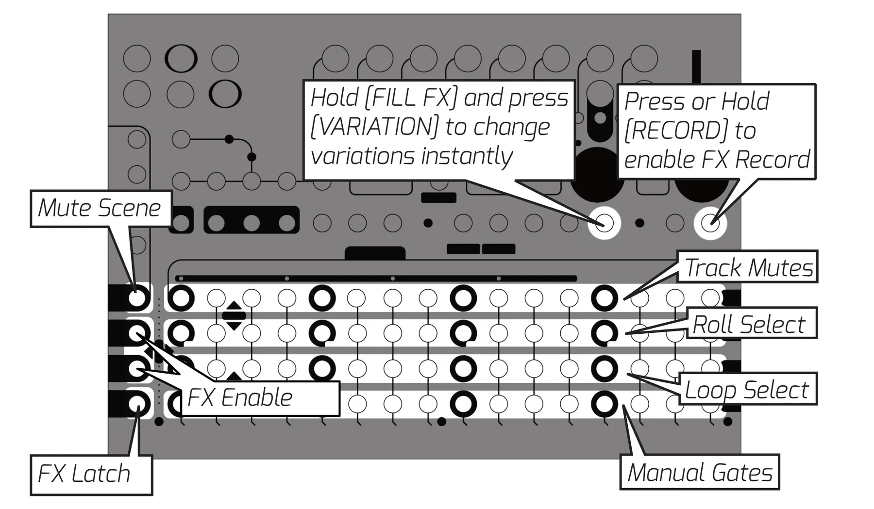
Instant: Hold [FILL FX] and press the [VARIATION] you would like to play. The variation will begin playing immediately from the current playhead position.
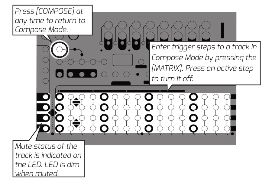
5.2Compose Mode
Compose Mode is considered to be the main or default mode of Metron. The four rows of the matrix correspond to the four tracks in the current TRACK GROUP.
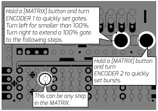
5.2.1Quick Burst / Quick Gate
The user can quickly enter burst steps without ever leaving Compose Mode by holding the [MATRIX] step and turning ENCODER 2. The burst type will show on the CURRENT STEP display.
A similar function is also extended to gates that allows the user to quickly enter long gates. Hold the corresponding [MATRIX] step and turn ENCODER 1. Turning the encoder to the left will make a gradually decreasing gate on the held step. Turning to the right will set the step to 100%. Continuing to turn the encoder will push 100% gates to the following steps extending to a multi-step gate.
5.3Voltera Basic Functions
This section contains the functions that are available to Voltera when Metron is in Compose Mode.
5.3.1"Last Event" Method of Operation
Voltera is a "last event" sequencer. This means that the outputs will always hold the voltage of the "last event" sent to them. Setting a step will not send an event to the output until the sequencer plays that step.
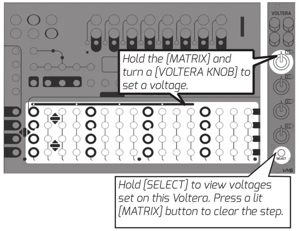
5.3.2Setting a Voltage on a Step
Set a Voltage on a step by holding a Metron [MATRIX] button and then turning the [VOLTERA KNOB] associated to the output the user would like to set the voltage on. The voltage or quantized v/oct value will be displayed on Metron's [CURRENT STEP DISPLAY] as well as Voltera's [TRACK LED].
5.3.3Audition Step While Setting Voltage
Pressing the [SELECT] button before or while setting a voltage on a step will "Audition" the voltage of that step. The output voltage will be directly set by the knob as long as the [MATRIX] button is held.
5.3.4Live Takeover
Holding the Voltera [SELECT] button on Voltera before turning the [VOLTERA KNOB] will set the output to "Live Takeover." When this is enabled the [VOLTERA KNOB] directly sets the voltage of the corresponding output. Regardless of the state of the sequencer. When the user releases the [SELECT] button the output will return to normal sequencer driven operation.
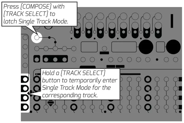
5.4Single Track View
The user also has the option to display four pages of a single track across the four rows of the MATRIX. This is referred to as Single Track View. Temporarily enter this view by holding the corresponding [TRACK SELECT] button. Latch this view by then pressing [COMPOSE] or vice versa.
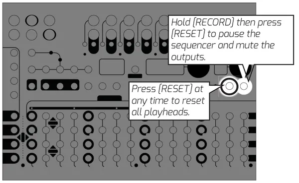
5.5Reset / Pause
Pressing this button will immediately reset all playheads inside the unit. It will also force any requested memory loads or follow actions to happen immediately. The RESET function is available from all modes in Metron, except for when the [RECORD] button is held. Holding [RECORD] and pressing [RESET] will pause the sequencer and mute the outputs. Repeat this button combination to unpause.
5.6Duplicate
DUPLICATE is one of the most essential functions to working quickly in Metron. Data types are arranged hierarchically. Anything lower in the hierarchy can take the data of something higher in the hierarchy, E.G. a user can copy a variation to a single track.
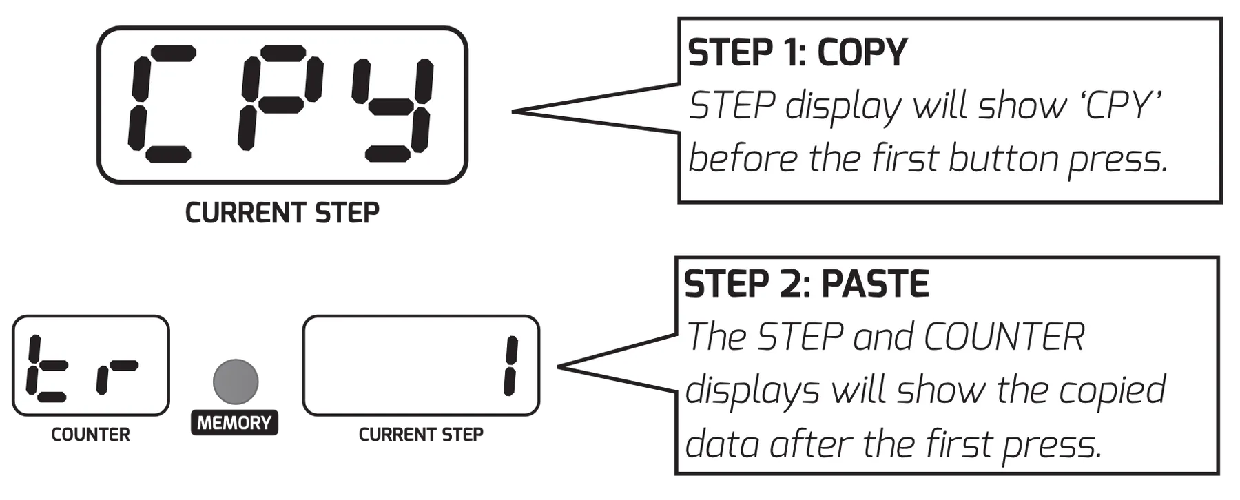
All of Metron's DUPLICATE functions are performed using a similar button combination. The user enters Duplicate Mode by holding [DUPLICATE]. The sequence of buttons pressed after entering Duplicate Mode determines the data that will duplicate. First press is Copy and subsequent presses are Paste. Paste actions will continue until [DUPLICATE] is released, unless otherwise noted in the following section.
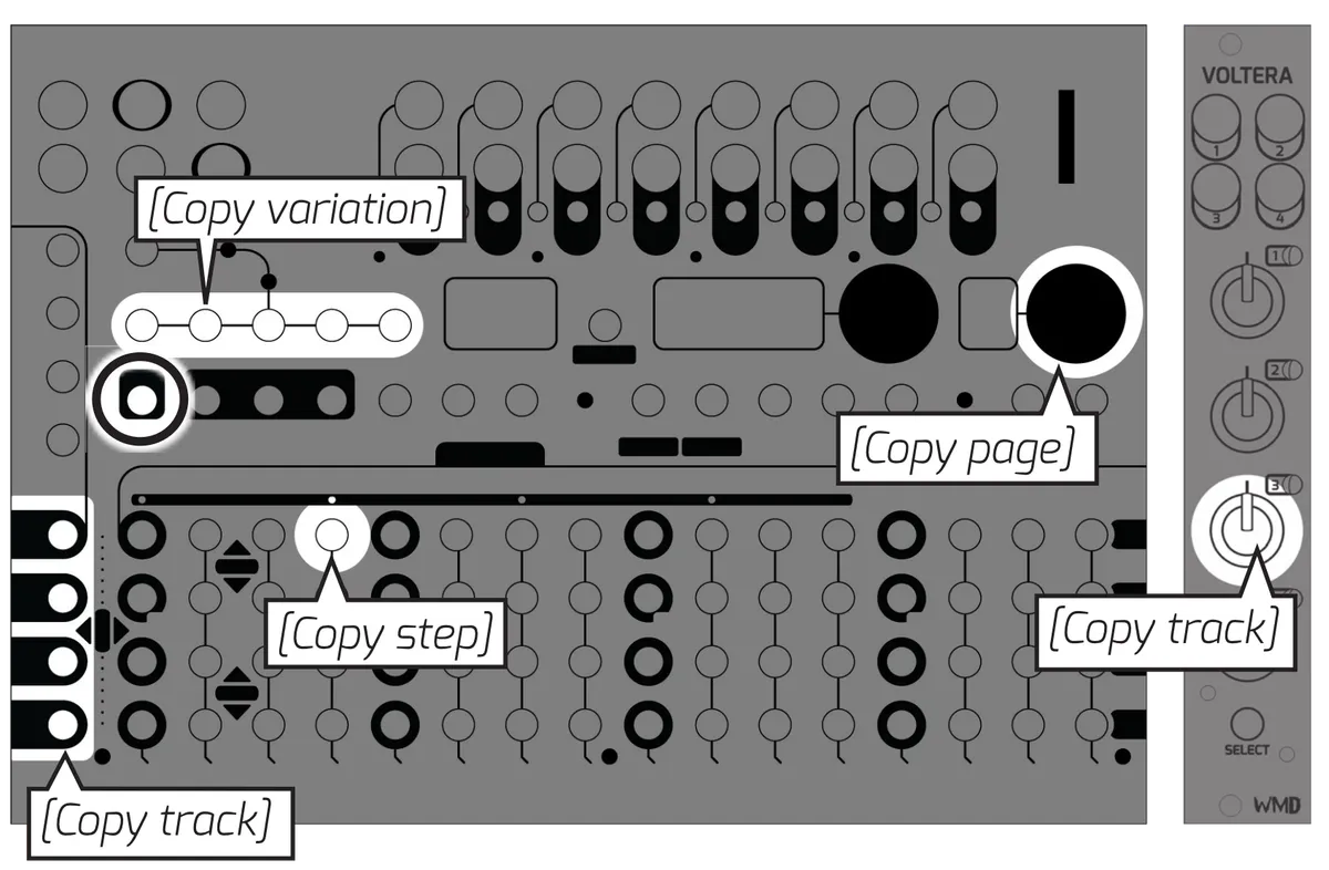
| COPY | PASTE |
|---|---|
| VARIATION | VARIATION PAGE TRACK |
| PAGE | PAGE TRACK |
| TRACK | TRACK |
| STEP | STEP TRACK |
fig. 5.3
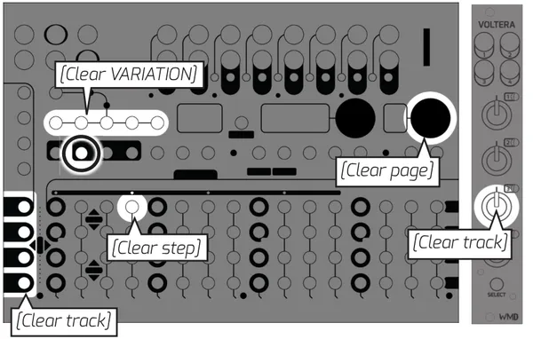
5.7Clear
Quickly clear data by holding [CLEAR] and pressing the [VARIATION], [TRACK SELECT], any [MATRIX] button, or [ENCODER 2] corresponding to the data you would like to clear.
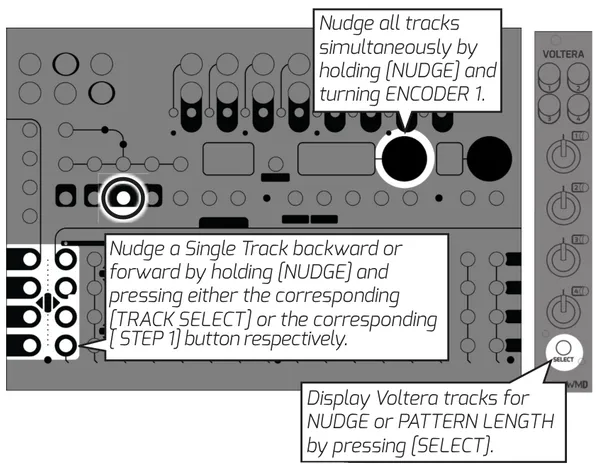
5.8Nudge
Metron has the ability to nudge a single track, or all tracks at once. Nudge data wraps at the track's pattern length, and the original first step of the pattern will blink in order to let the user know how far they've nudged the pattern.
5.9Pattern Length
Every track in Metron can have its own independent pattern length.
To set a single track's pattern length hold [PTN LENGTH] and press the [MATRIX] button that corresponds to the desired last step on that track.
To set all tracks to the end of a page hold [PTN LENGTH] and press [ENCODER 2] while viewing the page you would like to end on.
Increase or decrease the length of all tracks simultaneously by holding [PTN LENGTH] and turning ENCODER 1. Set all tracks to the length of the longest track by holding [PTN LENGTH] and pressing [ENCODER 1].
5.10Memory
Metron's memory can contain up to 512 sessions, addressed in banks of 64 across 8 projects. The memory interface is accessed by pressing the [MEMORY] button.
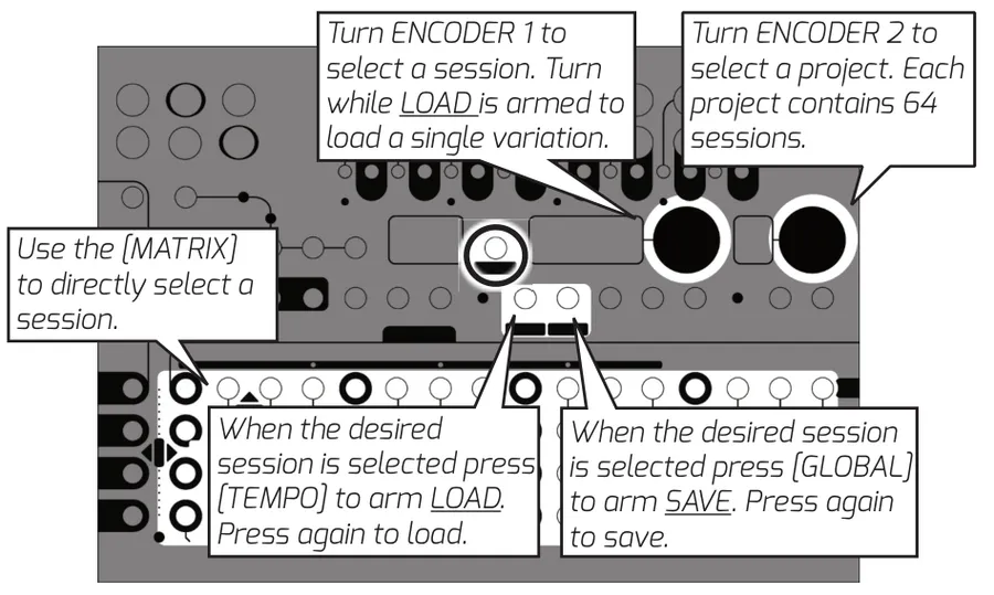
5.10.1Save Session
Arm SAVE SESSION by pressing [GLOBAL] in Memory Mode. The display will show 'S' followed by the currently selected slot. Use ENCODER 1 to select a new slot if desired. Press [GLOBAL] again to save the session.
5.10.2Load Session at End of Bar
The normal loading procedure will load the session at the end of the next bar, or the end of the pattern if it occurs before the next bar. First select the session you would like to load using the [MATRIX] or ENCODER 1. Arm LOAD by pressing [TEMPO]. The step display will show 'L' followed by the selected slot. Press [TEMPO] again to load.
5.10.3Load a Blank Session
Loading a session from an empty memory slot will load and automatically save a new, blank session. Global settings from the current session will be applied to this session.
5.10.4Quick Load
This feature has been removed in Firmware 1.6 to enable the ability of loading blank sessions in Memory mode.
5.10.5Load Variation Instant
The user also has the option to load a single variation or all 5 variations instantly. All other session information is ignored when a variation is loaded.
To load a variation follow the steps to arm LOAD (see above). Before pressing [TEMPO] a second time, turn ENCODER 1 to select the desired variation, or all 5. If you are loading a single variation, it will load into the current variation being edited. Press [TEMPO] to initiate the VARIATION LOAD. The data will load instantly.
5.10.6Quick Load 5 Variations - Instant
Quickly load all variations while playing session data by holding [TEMPO] and pressing the [MATRIX] button corresponding to the desired session. The variation data will load instantly, and Memory Mode will exit.
5.10.7S.BUS Loading
Metron responds to Select Bus program change messages by instantly loading a session. Enable this feature by setting S.BUS to 'IN' in GLOBAL settings.
5.10.8Clear Memory Slot
Hold [CLEAR] and press the corresponding [MATRIX] button.
5.11Record
Quickly record manual triggers and gates to a track by holding or pressing [RECORD] then tapping the corresponding [TRACK SELECT] button.
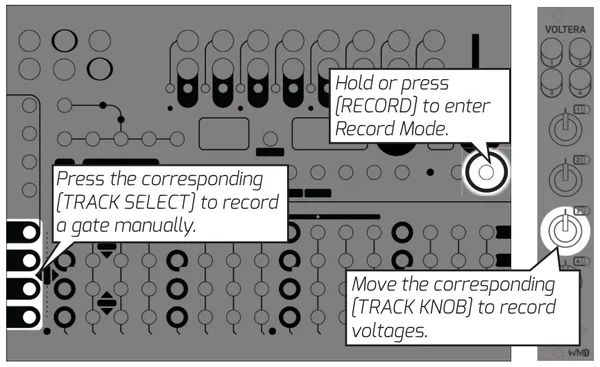
5.11.1Record Manual Gate
Hold or press [RECORD], then press the corresponding [TRACK SELECT]. Manual gate recording is quantized to the 16th note on the standard grid.
5.11.2Record Voltages
Hold or press [RECORD], then move the corresponding [TRACK KNOB]. The last knob position before the sequencer moves to the next step will be the stored value.
6Advanced Sequencing
This section describes the deeper sequencing features of Metron.
6.1Burst Mode / Gate Mode
Burst and Gate Modes allow the user to quickly enter predefined microstep data. Press and hold [BURST] or [GATE] to enter the corresponding mode. Step data entered in these modes are equivalent to microstep data and vice versa.
The STEP DISPLAY shows the displayed step type. Turning ENCODER 1 changes the displayed step type.
| Burst Types | Gate Types |
|---|---|
| 2 Burst | 15% |
| 3 Burst | 25% |
| 4 Burst | 50% |
| 75% | |
| 100% |
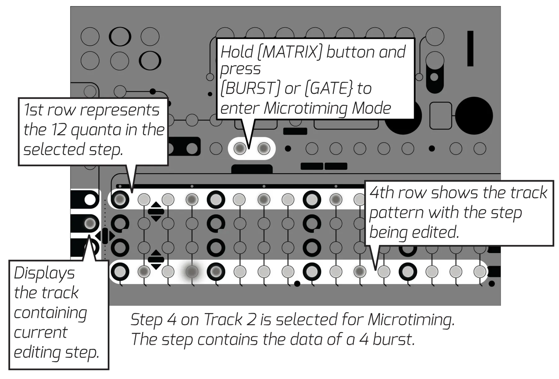
6.2Microtiming
Microtiming Mode allows the user to access the full 48ppqn resolution Metron offers. The microstep view uses the fourth row of the MATRIX to show the pattern of the track that contains the current editing step. The current editing step will be blinking. The first 12 steps of the first MATRIX row are used to represent the time of one step divided into 12 equal quanta. The TRACK SELECT buttons display the track that contains the current editing step. Press any of the first 12 steps in [MATRIX] row 1 to toggle the microstep.
6.2.1Enter Microtiming Mode
Holding a [MATRIX] button in Compose Mode and pressing [BURST] or [GATE] will enter Microtiming Mode for the selected step.
6.3Random Mode
Random Mode gives the user access to Metron's probability engine, as well as Metron's random pattern generation feature. These features are powered by a true analog random generator. Metron has the ability to assign a probability percentage to any step of the 16 tracks regardless of the step data contained. This is the percentage probability that the data on the step will play. Metron extends this core feature by adding an alternate event that takes place when the main event doesn't, as well as the ability to apply group probability to a group of steps so they either all happen or don't.
6.3.1Random Pattern
Generate random patterns at the Track or Variation level by holding [RANDOM] and pressing the corresponding [TRACK SELECT] or [VARIATION] button.
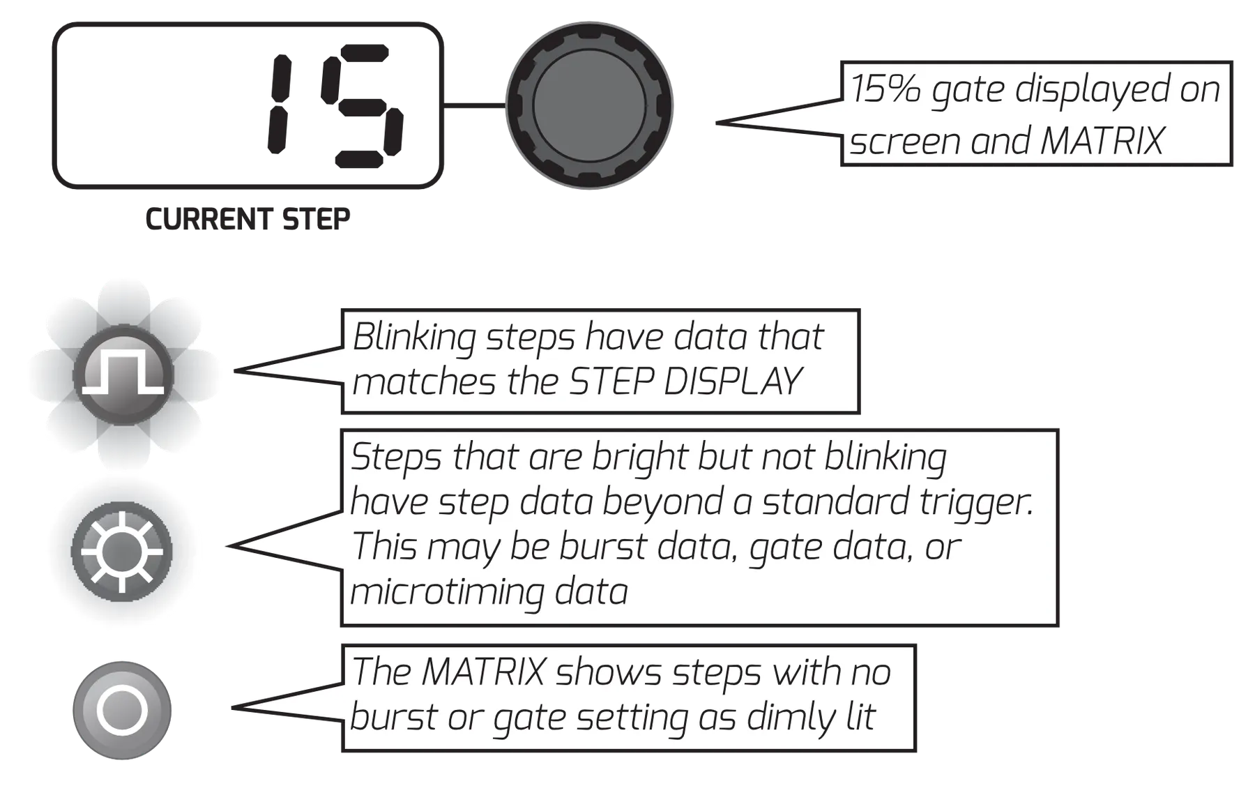
6.3.2Probability
Enter Random Mode by pressing [RANDOM]. The Random Mode display is similar to the Burst and Gate Mode displays. The STEP DISPLAY shows the displayed probability. Turning ENCODER 1 changes the displayed probability. The MATRIX shows steps with no probability setting as dimly lit. Steps that are flashing have the probability setting shown on the step display. Steps that are bright but not blinking have probability set to a different value than the one shown on the display. Press a [MATRIX] button to set the step to the probability shown on the display. Pressing it a second time will remove the probability data while preserving the pattern data.
6.3.3Group Probability
The final amounts listed on the STEP DISPLAY are the letters A,B,C, and D followed by a number, E.G. "A.25". These represent Group Probability. All steps set to the same letter share a "coin toss." The probability "coin toss" takes place at the beginning of the variation. Change a group's probability setting by pressing [ENCODER 1]. A group can also use another group to define its probability setting; E.G. steps set to A.B will only play if group B fails to play.
6.3.4Alternate Event
View the alternate event page by pressing [ENCODER 2]. The STEP DISPLAY will now show triggers, bursts, and gates. These events can only be placed on steps that already have a probability assigned to them. These steps will be lit brightly.
| Probability Amounts | Alternate Events |
|---|---|
| 10% | Trigger |
| 25% | 2 Burst |
| 50% | 3 Burst |
| 75% | 4 Burst |
| Group A | 15% Gate |
| Group B | 25% Gate |
| Group C | 50% Gate |
| Group D | 75% Gate |
| 100% Gate |
6.4Triplet
Metron's engine allows the user to freely mix triggers contained on a triplet grid and standard grid at quarter note resolution. When a quarter note is set to triplet, only the first 3 steps in that quarter note will be lit. The fourth step can contain data, but it will be ignored during playback. Set a quarter note to triplet by accessing Triplet Mode and pressing the corresponding [MATRIX] button. Triplet can also be enabled for an entire track or variation by pressing the corresponding button while holding [TRIPLET].
6.5Per-Track Shuffle
Metron offers the ability to shuffle clock on a per-track basis. These settings are saved within the session.
You can push every other step on a track back in time by up to 15 microsteps by holding the corresponding [TRACK SELECT] and turning Encoder 1. The offset will be displayed in microsteps on the step display.
Hold [CLEAR] and press [TEMPO] to set all tracks back to no shuffle.
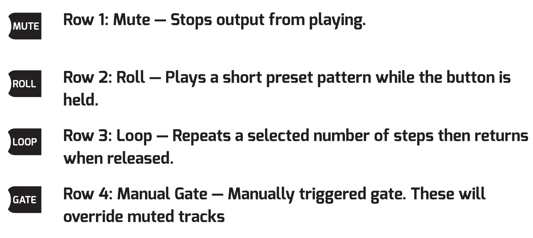
7Fill FX
The Fill FX mode is designed to give the user access to performance tools for generating fills and new patterns on the fly. The four rows of the MATRIX each represent a different tool. Row 1 is Mute, Row 2 is Roll, Row 3 is Loop, Row 4 is Gate.
7.1Mute
Pressing any button in this row will toggle the current mute status of the selected track. Mute will stop anything from playing at the output, except for manual gates.
7.1.1Recall Mute Scenes
Hold [TRACK SELECT 1] to enable the Mute Scene selection, and press a [MUTE] button to select a scene. Mute Scenes allow the user to set the mutes to a known status. All mute scenes are set to ON for all tracks by default. Recalling this scene would set all outputs to unmuted regardless of their previous status.
7.1.2To Set a Mute Scene
Set the mutes to the desired configuration. Hold the [MUTE] button that corresponds to the desired scene slot and then press [TRACK SELECT 1]. Mute Scenes are saved with Session Memory. The last mute scenes set in the system will be loaded on power up.
7.1.3Mute Scene Track Enable
By default, all tracks are enabled to respond to Mute Scenes. The user can disable this for a track on the fly by turning off the Mute Scene Track Enable. You can access this by holding Track Enable [TRACK SELECT 2 or 3] and pressing the corresponding [MUTE] button. Enabled tracks are lit, disabled tracks are dim.
7.2Roll
Roll switches the current playing pattern to a known stored pattern that starts when a [ROLL] button is pressed. Access Roll by pressing any of the [MATRIX] buttons in row 2.
7.2.1Roll Track Enable
Roll can be disabled for certain tracks by holding Track Enable [TRACK SELECT 2 or 3] and pressing the [ROLL] button that horizontally corresponds to the track you would like to disable.
7.2.2Roll Pattern Replace
Metron is filled with a selection of useful default roll patterns, but the user can replace any of these patterns as they please. To replace a pattern, first compose a 16-step replacement pattern in any track of Compose Mode. Feel free to use triplets as you please. When you are happy with the pattern, hold the corresponding [TRACK SELECT] and press the [FX FILL] button. Before releasing [TRACK SELECT], turn ENCODER 1 until the STEP DISPLAY shows the Roll selection you would like to replace. Press [ENCODER 1] to select and save. Roll patterns are stored in the Global Settings file.
7.2.3Roll Pattern Special Track Enable
The Roll feature can be pushed into advanced territory by using the Special Track Enable feature. This feature allows a roll to contain its own track enable assignment. This allows you to decouple certain rolls from the main track enable and use them simultaneously. Access this feature by holding the [ROLL] you would like to set a Special Track Enable on, and pressing Track Enable [TRACK SELECT 2 or 3]. Row 2 will begin to flash. If all lights in the row are flashing, the Roll refers to the main track enable. Press any of these buttons to set the Special Track Enable for the selected Roll.

7.3Loop
The Loop effect allows the user to repeat a selected number of steps starting from the point the FX enabled. When disabled, the playhead returns to the position it would be at if the effect was never triggered.
7.3.1Loop Track Enable
Use the Track Enable function to toggle whether Loop will effect the corresponding track. Hold Track Enable [TRACK SELECT 2 or 3] and press the corresponding [MATRIX ROW 3] button to toggle enable. Enabled tracks are brightly lit.
7.4Latch FX
Latch an effect by holding it and pressing the Latch button [TRACK SELECT 4]. Holding Latch then pressing the effect will also work. Press the effect again or press Latch to disable the latch.
7.5Instant Variation Change
Holding the [FX FILL] button while selecting a variation will instantly jump to that variation without affecting the playhead. Use this feature to punch into variations and live "cut" them together.
7.6Record FX
Some of the functions in the FX Fill Mode can be recorded. This includes Roll, Loop, and Instant Variation Change.
To record an effect, enable recording by pressing or holding the [RECORD] button, then enable the effect you would like to record. Effects running before RECORD was enabled will be disabled. Only one Roll may be recorded at a time. When recording instant variation change, any change will record to the variation that was active when RECORD was enabled.
8Special Functions
This section contains information on some of Metron's unique helper functions. These functions are designed to inspire the user and help generate new ideas quickly.
8.1Compose Chain
This feature allows the user to chain the information from multiple variations together and paste it into the editing variation. Use this feature by holding the [COMPOSE] button, and pressing the [VARIATIONS] you would like to chain. The previous pattern in the editing variation will be buffered and continue to play until the first variation of the chain is pressed.
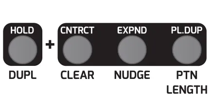
8.2Duplicate Pattern Length (DUP.PL)
This feature helps the user extend their pattern length by copying the current pattern and duplicating it out to the new pattern length. Use this feature by first going to the page you would like to extend to. Then hold the [DUPLICATE] button and press [PTN LENGTH]. This will extend all tracks to the end of the viewing page. This function can be applied to tracks individually by holding [DUPLICATE], pressing the corresponding [TRACK SELECT] button, and then pressing [PTN LENGTH].
8.3Step to All Pages
This feature allows the user to quickly place a step on all pages. Use this function by holding [ENCODER 1] and pressing a [MATRIX] button. This function works in Compose Mode, Burst Mode, and Gate Mode.
8.4Contract
CONTRACT allows the user to destructively edit the data as if it were being played at 2x. Use this function by holding [DUPLICATE] and pressing [CLEAR]. Apply this function to a single track by holding [DUPLICATE], pressing the corresponding [TRACK SELECT], and then pressing [CLEAR].
8.5Expand
EXPAND allows the user to destructively edit the data as if it were being played at ½ speed. Use this function by holding [DUPLICATE] and pressing [NUDGE]. Apply this function to a single track by holding [DUPLICATE], pressing the corresponding [TRACK SELECT], and then press [NUDGE].
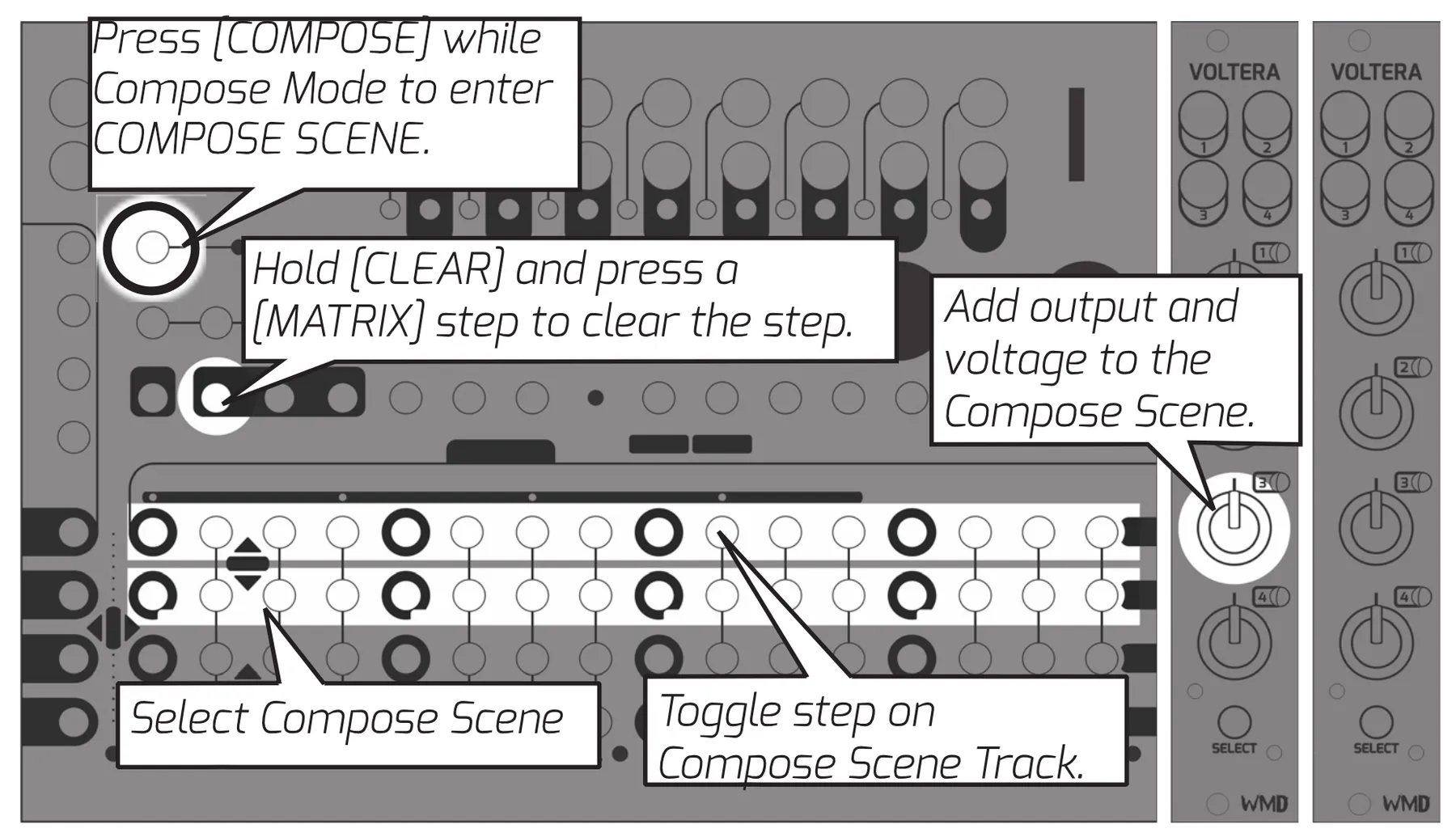
8.6Compose Scene
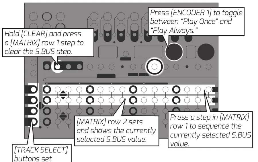
Compose Scenes are 16 sequencable voltage presets for Voltera expanders.
Create a Compose Scene by holding any [MATRIX] button in row 2 and turning the [TRACK KNOB] associated with the output you would like to make a Compose Scene for. Holding this button will audition the scene on the selected outputs as long as the Compose Scene button is held.
Sequence these scenes by pressing the [MATRIX] buttons in row 1. The last select scene will be lit on row 2. This scene will be placed in the sequence when row 1 is pressed. Steps with scene data that is not the currently selected scene will show with a dim LED. Scenes will take priority when Scenes and Voltages are set on the same step.
9Settings
9.1Tempo and Shuffle
Access Metron's Internal Clock settings by holding [TEMPO] and turning the encoders. ENCODER 1 changes TEMPO. ENCODER 2 changes SHUFFLE AMOUNT. Quickly set Metron back to 50% shuffle by pressing [ENCODER 2]. The clock input can also be switched between Internal and External in this mode by pressing [ENCODER 1].
9.2Global Settings
Metron offers a number of Global Settings that allow the user to further refine their experience while using Metron. Access Global Settings by pressing the [GLOBAL] button. Use ENCODER 2 to select the setting, and ENCODER 1 to change the setting's value.
| ENCODER 2 = SELECTION | ENCODER 1 = VALUE |
|---|---|
| Clock Internal / External | Set the clock to Internal or External* |
| Character Format | Display time in decimal* (base 10) or hexadecimal (base 16 [0-F]) |
| Step Count Direction | Steps and Bar counter count up or down |
| Brightness | A. High B. Med C. Low |
| Trigger Length | Time length of a single microstep. 1ms, 2ms, 4ms, 8ms, 1/36th clock, 1/12th clock*. |
| Gate Delay | Set in increments of 5 microseconds. Max delay of 2ms. |
| PPQN | Clock "Pulses per quarter note" setting. 4, 8, 12, and 24 PPQN settings. |
| Clock Out Always | Yes or no to send clock output when sequencer is paused |
| Reset Input | Determines whether the reset input responds to a trigger*, or expects a din sync style start/stop signal to run. |
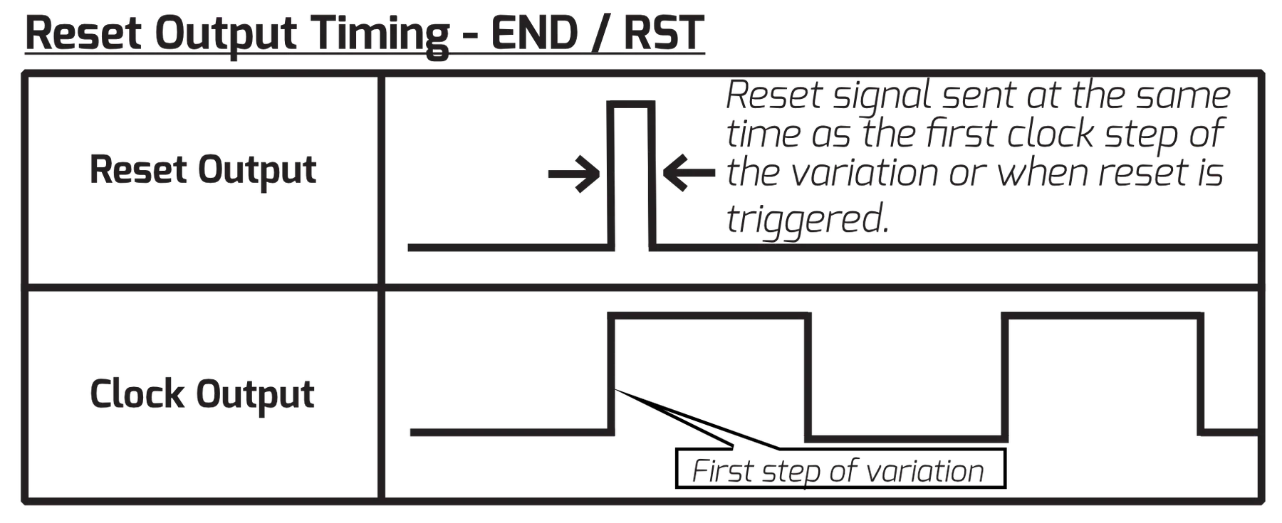
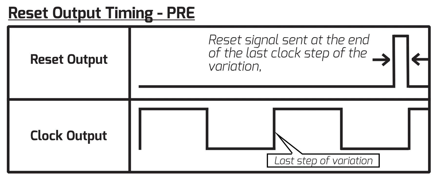
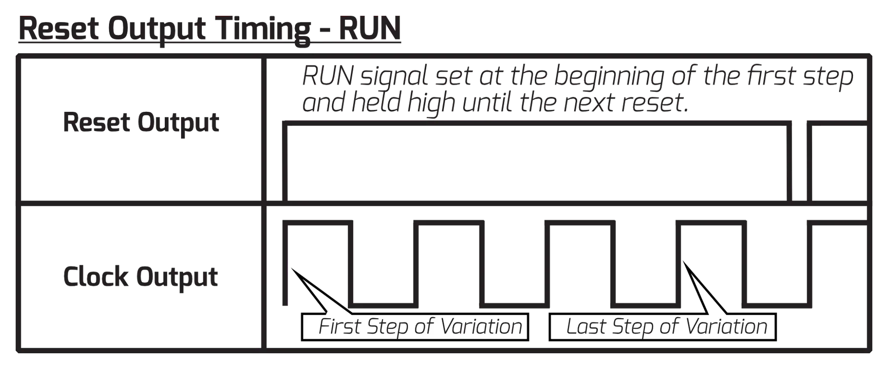
| Reset Output | END* - sends a reset signal at the end of the variation. RST - sends a trigger only when a Reset signal is received. PRE - Sends the reset signal slightly before step one, to be more compatible with other sequencers. RUN - the output stays high. |
| S. Bus Direction | Sets whether Metron will send or receive S.Bus Messages. 'IN' receives, 'OUT' sends, 'OFF' ignores. |
| Initialize Settings | Click [ENCODER 1] to initialize the settings on the current project to default. |
| Firmware update | Click [ENCODER 1] to force Metron to update. Firmware file must be present on the SD card. |
| Version | Current Step Window shows the firmware version currently loaded. |
*Default Setting
9.2.1Voltera Settings
Voltera's settings are also accessed in the global menu. These settings are saved per project.
| Setting | Description |
|---|---|
| Voltera track smoothing | While in the Global menu, select a voltera track by turning the correlated knob and press [ENCODER 1] to enable smoothing on that track. |
| Voltera knob input Range | While in the [GLOBAL] menu, turn a KNOB on Voltera to select that track and select a quantization setting. |
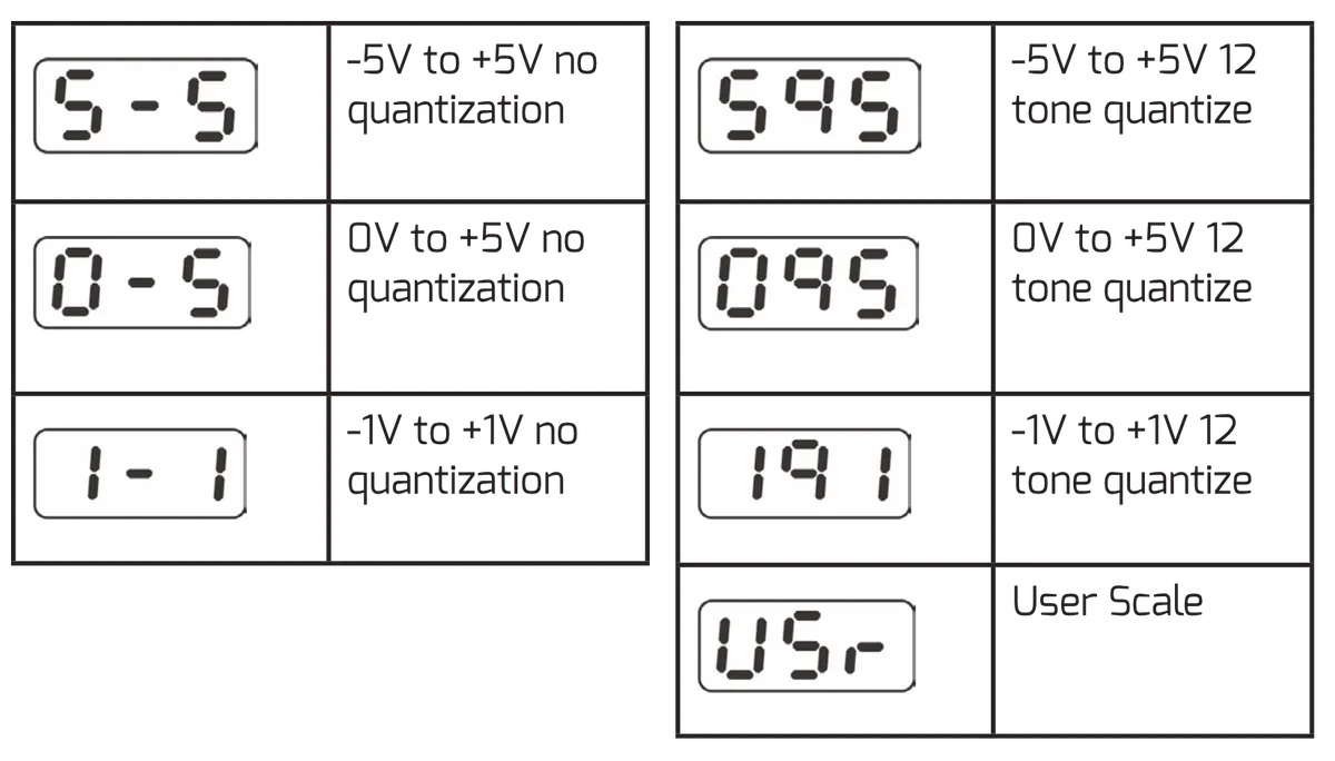
9.3Voltera Knob Input Range
Voltera offers a number of knob input ranges for more detailed entry of control voltage data. Voltera's outputs always offer a -5V to +5V voltage range. The sequence will play as it was written regardless of the current input range. Enter this mode by moving any Voltera knob while viewing Global Settings.
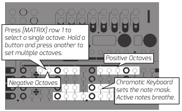
9.4Voltera User Scale
The Voltera user scale allows you to set a custom scale with a custom octave range per output. The user scale is saved and recalled on power up as well as when a session is saved or loaded. Active notes and octave ranges will blink with a breathing pattern.
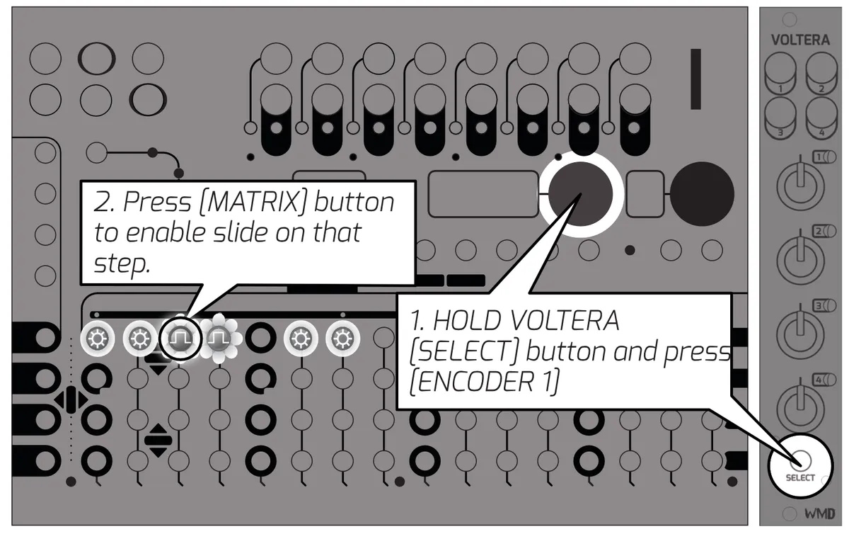
9.5Voltera Per Step Slide
Voltera offers the ability to slide from one step to the next, similar to popular acid-style sequencers. To enter this display mode, HOLD the [SELECT] button on the Voltera you want to enable slides on and press [ENCODER 1].
Continue to hold [SELECT] and use the [MATRIX] buttons to enable a slide on the desired step for the desired Voltera track. Step led is lit to show voltage is enabled on that step and will blink to indicate slide is active.
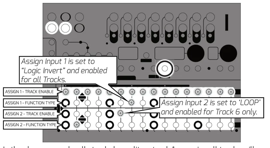
10Assignable Inputs
Assignable Inputs enable external interaction with Metron's sequencing. Each Assignable Input can be assigned one of 16 different functions. These functions can be enabled or disabled on a per track basis.
Press the Global Settings button to display the assignable input functions and select functions using the MATRIX buttons.
Functions are triggered when an external signal is received through the assign in jacks.
10.1Assign Functions
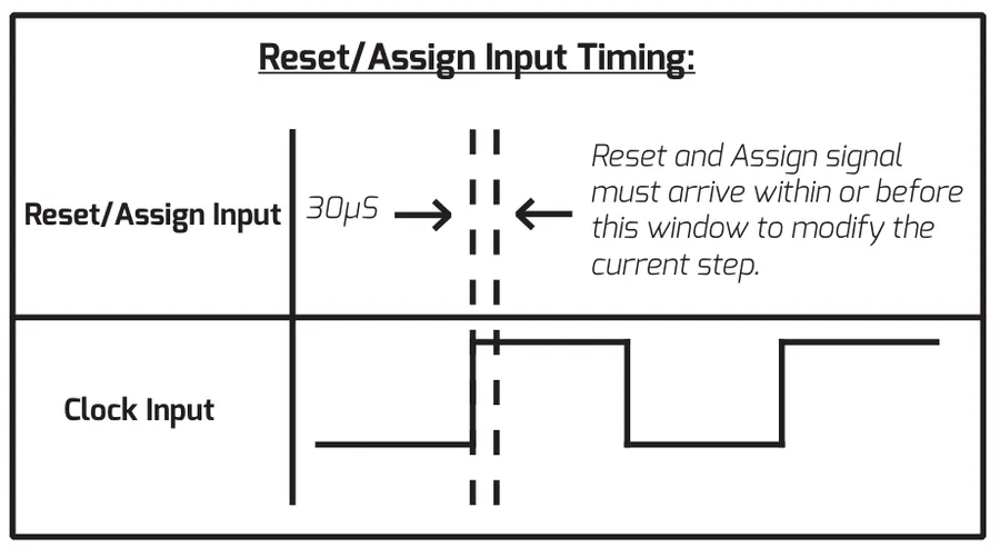
See the chart on the next page for a full list of functions. Functions labeled (A) will take place as soon as they are triggered. Functions labeled (B) will be queued up to occur in sequence as soon as they are triggered. Functions labeled (C) will take place at the next clock step after they are triggered. Functions labeled (D) will be queued up to occur in sequence at the next clock step.
| Step Column | Function | Description |
|---|---|---|
| 1 | ROLL (D) | CV Controlled Roll. 1V = 1/4 Note, 2V = 1/8 Note, 3V = 1/16 Note, 4V = 1/32 Note |
| 2 | LOOP (D) | CV Controlled Loop. 1V = 8 Steps, 2V = 4 Steps, 3V = 2 Steps, 4V = 1 Step. |
| 3 | RESET (A) | Resets enabled tracks. |
| 4 | ERASE (D) | Erases steps at the playhead for enabled tracks when the gate is high. |
| 5 | LOGIC OR (B) | Combines the gate at the ASSIGN input with the pattern on enabled tracks. |
| 6 | LOGIC AND (D) | Enabled tracks will not play anything unless the ASSIGN input is also high. |
| 7 | LOGIC INV (D) | When the gate is high, steps with data turn off. Steps without data play as triggers. |
| 8 | RANDOM (C) | Generate a random pattern on selected tracks when the gate goes high. |
| 9 | REC QUANTIZED (B) | Records any high gate on the ASSIGN input. Quantized to 16th notes. |
| 10 | REC UNQUANTIZED (B) | Records any high gate on the ASSIGN input at 48ppqn resolution. |
| 11 | NUDGE FORWARD (C) | Nudge all steps on enabled tracks to the right by one when the gate transitions high. |
| 12 | NUDGE BACK (C) | Nudge all steps on enabled tracks to the left by one when the gate transitions high. |
| 13 | NEXT VARIATION (C) | Trigger the next variation to play at the end of the current variation. |
| 14 | PREVIOUS VARIATION (C) | Trigger the previous variation to play at the end of the current variation. |
| 15 | INSTANT NEXT VARIATION (A) | Move to the next Variation immediately without resetting playheads. |
| 16 | INSTANT RETURN TO VAR A AND RESET (A) | Move to Variation A immediately and reset playheads. |
| — | DISABLE | Assign type LED is off, input is ignored. |
11S.Bus
Metron has the ability to interact with modules that support the communication feature commonly referred to as Select Bus. Metron is capable of being a S.BUS master or slave, modifiable from Global Settings, accessed by pressing the [GLOBAL] button. When acting as a slave, Metron will recall one of the 64 memory sessions saved in your current project when it receives a change message.
The S.BUS feature reaches a new level of control when Metron is the master. Using the S.BUS mode accessed by pressing [S.BUS], the user can freely sequence change messages to compatible modules on the busboard.
This mode allows the user to send and sequence program change messages to compatible modules on the busboard.
12Metron Specs
Dimensions:
- Width: 36HP (182.75mm)
- Height: Eurorack 3U (128.5mm Panel, 112mm PCB behind panel)
- Depth Including Cables: 31mm
Power:
- 16 pin Eurorack standard power cable
- 90 Degree, Low Profile Connection
- Reverse Polarity Protected
- Do not connect power to expansion headers.
- Typical Power Consumption: +12V: 180mA, -12V: 0mA
- Maximum Power Consumption: +12V: 240mA, -12V: 0mA
- Start Up Time: 2.5 Seconds to splash screen, 6 seconds total
- Inrush Current: 50mA
Inputs:
- CLOCK IN, RESET IN: 100kΩ Impedance, Logic High, Schmitt Trigger, 2.2V Threshold
- ASSGN1 IN, ASSGN2 IN: 124kΩ Impedance, 0V to 5V Analog
- SyncBus normals to CLOCK IN, RESET IN jacks
- USB Mini: for catastrophic bootloader reinstallation, not expected to be used
- Norm/USB switch must be set to Norm for normal operation
- EXP (x2): Proprietary Expansion/Chain connector, 8 pins IDC
- Must have EXP TERM on either header if unused
- Must have EXP TERM (x2) at both ends of chain if used
Outputs:
- Channel Outputs 1-16: 470Ω Impedance, 0V or 10V Logic High
- Channels are simultaneously updated
- Channel LEDs reflect real-time output state
- CLOCK OUT, RESET OUT: 470Ω Impedance, 0V or 10V Logic High
- Select Bus: 50Ω Output Impedance, Active Low, 47kΩ Pull Up
- 3.3V and 5V compatible. Software Selectable inbound
Regulatory:
- RoHS, CE, & WEEE Compliant
- Made with Lead Free solder and processes.
- No animals were harmed in the making of Metron.
13Credits
The font family used in this manual is EXO, designed by Natanael Gama.
The WMD logo is derived from Cocaine Sans, designed by Christopher Hansen.
14Glossary
The terms here may be applied in specific ways for this module. They are defined as such to avoid confusion with the "dictionary definition" one might find elsewhere.
- BLINKING:
- When the LED quickly turns off and on as if controlled by a square wave.
- BURST:
- Multiple triggers sent per step, creating a "ratchet" like sound.
- BREATHING:
- When the LED cycles slowly on and off as if controlled by a triangle wave.
- LATENCY:
- Time delay between when a signal is received and when it is processed.
- MATRIX:
- The panel of 64 buttons that takes up the lower section of the sequencer's panel. These buttons are used to activate steps and control different features throughout.
- PLAYHEAD:
- A term for the virtual cursor keeping track of the sequencer's position in time, regardless of the visual cursor's position.
- POLLED:
- To check (devices, such as several computer terminals sharing a single line) in sequence for messages waiting to be transmitted.
- RISING EDGE:
- Rising edge means the event will only occur if the voltage goes from 0V to 3V or above. If the gate stays high, the event will not re-trigger until it goes low and comes back up.
- ROOT:
- Files stored in the "root" of a memory card that have no enclosing folder. The settings file is stored here as it applies to all project folders.
- SCENES:
- Essentially, these are presets of track mute settings that can be recalled at any time.
- SESSION:
- Refers to all of the data contained within one of Metron's 64 save slots. A session contains the pattern data for 5 variations, 16 Mute Scenes, and settings for Internal Clock and Assign Input.
- VARIATION:
- A pattern stored on METRON is referred to as a variation. When loaded into a variation slot, these can be played, viewed, and edited at any time.
15Appendix
More technical specifications about Metron.
15.1Reset Output Behavior
See graphics below for explanation of reset output timing.