Geiger Counter
Digital destruction Eurorack module with CV control over every parameter
1Introduction
Thank you for purchasing the Geiger Counter. Welcome to the world of digital distruction.
The Geiger Counter is a bit-crushing distortion and waveshaper. Your signal passes through an analog preamp with Gain and Tone controls, then into a digital heart that re-samples it, reduces its bit depth, and reshapes it through one of many wave tables. In the Eurorack version every parameter is available for CV modulation, and the module is fully DC coupled so it will process audio and control voltage alike.
2Installation
Use a 16 pin to 10 pin ribbon cable for installation. +12 volts is towards the top of the module. The Geiger Counter uses up to 60mA at +/-12 volts. Plug in the ribbon cable and then secure the module using four M3x6 mm screws. The cable should have the red stripe pointing down on both the module and on standard Doepfer style racks.
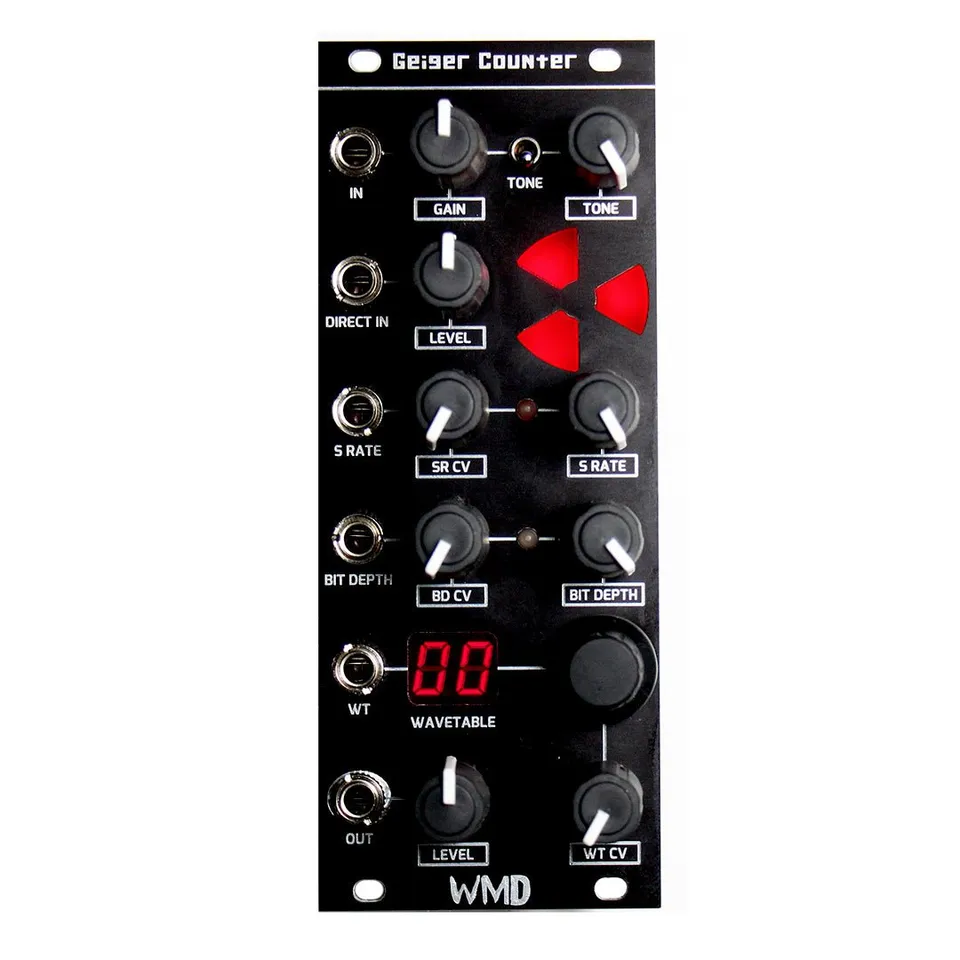
3Front Panel Overview
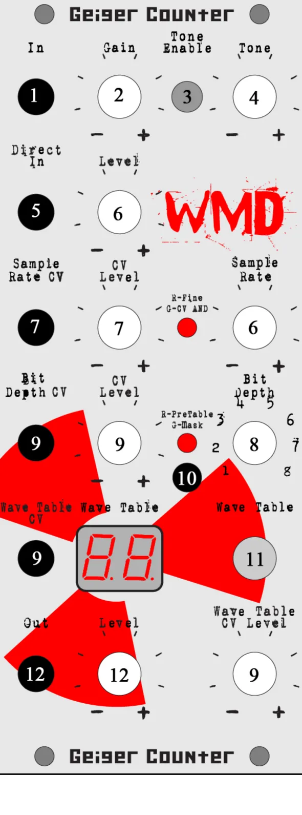
- Input: Input to the preamp section.
- Gain: Sets the amount of preamp gain feeding the digital section. Low settings stay clean; high settings brickwall the signal for sustain.
- Tone Enable: Switches the tone control in or out of the preamp circuit.
- Tone: Blends muffled low-mids with chimey, clear upper mids and highs feeding the digital section.
- Direct Input: Injects a signal after the preamp, bypassing the Gain and Tone circuits. The Geiger is DC coupled from this point on.
- Level: Attenuates the level coming out of the preamp to add or remove hard clipping going into the digital section.
- Sample Rate CV and CV Level: CV input and attenuator that modulate the Sample Rate. With no cable patched, the Sample Rate knob sets the rate directly.
- Bit Depth: Reduces the vertical fidelity of the signal, introducing quantization distortion.
- Bit Depth CV / Wave Table CV and CV Level: CV inputs and attenuators that modulate the Bit Depth and the Wave Table around the positions set by their knobs.
- CV Bias Adjustment: Trim pot that sets the CV bias, calibrated at the factory. See Calibration below.
- Wave Table: The two-digit display and rotary encoder select the active wave table. Push the encoder to change modes.
- Out and Level: The final output, +/-5Vpp. The Level control sets the output volume.
4Preamp Section
4.1Gain
Low settings provide clean tones with no distortion at all, while high settings will brickwall your signal for great sustain. Use the Gain control as a coarse setting for getting the desired tone from the selected wave table.
4.2Tone Enable
This switch removes the tone control from the preamp circuit. When down, the tone control sucks some volume from the gain, and this allows the pure ultra hot signal to go directly into the Wave Table. If a very clean tone is desired, set to Disable and adjust the gain to get the right amount of breakup. For most wave tables, disabling the Tone will produce completely different sounds by brickwalling to the extremes of the tables faster.
4.3Tone
The Geiger Counter's tone control blends muffled low-mids with chimey and clear upper mids and highs, providing a very large range of sounds in junction with the Gain. All the way down and the sound is muffled and grungy with little upper harmonic content. The middle range is smooth and full bodied. The top range cuts the lows completely for only upper harmonic content. Use the Tone to fine tune the sound of the wave table.
4.4Direct Input
Direct Input bypasses the preamp. The Geiger is DC coupled from this point on, so it will pass control voltages as well as audio into the digital section.
4.5Level
This control attenuates the level coming out of the preamp to add or remove hard clipping going into the digital section of the Geiger Counter.
5Digital Section
5.1Sample Rate
Controls the length of the samples your signal is converted into. Full up and the Geiger Counter samples faster than a CD. Dial it down a little and you'll lower the fidelity and frequency response, adding overtones and difference frequencies. Down a little produces some very nice chimey clean tones. Down more and higher notes disappear into chaos, all the way down to 240Hz. The LED when RED indicates that the range is reduced to the upper part.
The Sample Rate CV input and CV Level control take standard control voltages to modulate the Sample Rate. When a cable is inserted, the Sample Rate knob on the right is used to set the center frequency about which the CV signal modulates. When the LED is GREEN, the CV signal is logically ANDed to the Sample Rate knob setting.
5.2Bit Depth
Reduces the vertical fidelity of your signal. This introduces quantization errors that create distortion. When the LED is GREEN, your signal is MASKed by the Bit Depth setting: this creates vertical gaps in the signal, introducing uneven quantization errors, adds lots of distortion, but can be used to clean up noise and tone shape. When the LED is RED, the Bit Depth operation occurs before the Wave Table modulation; this allows you to tone shape the response of the Wave Table.
The Bit Depth CV and Wave Table CV inputs and CV Level controls take standard control voltages to modulate the Bit Depth and the Wave Table controls. When a cable is inserted, the Bit Depth and Wave Table knobs control the center frequency at which the CV modulates around.
5.3Wave Table
The display and rotary encoder control the wave table setting. The Wave Table is like high-school algebra applied to your signal, running it through a math function adding distortion, gain, harmonics and mayhem. The more vertical action in each wave table, the more harmonics are produced. The signal is at rest in the middle, horizontally on each image.
6Output
Out and Level output the final signal at +/-5Vpp. The Level control reduces the volume of the Output.
7Calibration
7.1CV Bias Adjustment
This trim pot sets the CV bias. To set, turn the Wave Table CV Level and the Output Level knobs down. Plug a patch cable between the Wave Table CV and the Output. Turn the trim pot until the Wave Table reads 80. This is calibrated at the factory.
7.2Output Bias Adjustment
On the back of the Geiger near the power connector is a blue trim pot. This adjusts the DC offset of the output stage. It should be set AFTER the input bias pot, with no signal, Direct In level all down, and output level all up, to 0.00VDC. This is calibrated at the factory.
8Specifications
Power:
- 16 pin to 10 pin ribbon cable
- +12V is towards the top of the module
- Reverse Polarity sensitive: do not reverse the power cable
- Typical Power Consumption: up to 60mA at +/-12V
Inputs & Outputs:
- In: preamp input
- Direct In: DC-coupled input bypassing the preamp
- Sample Rate CV, Bit Depth CV, Wave Table CV: standard control-voltage inputs
- Out: +/-5Vpp output
Controls:
- Gain, Tone, Tone Enable switch, Level
- Sample Rate with CV Level, Bit Depth with CV Level
- Wave Table encoder with two-digit display and Wave Table CV Level
- Output Level
9Support
WMD is located in Denver, CO. Reach us by phone at 303-549-9205 or by email at sales@wmdevices.com. For more on the Geiger Counter, including video demos, visit the product page.