Digital VCA MKIII
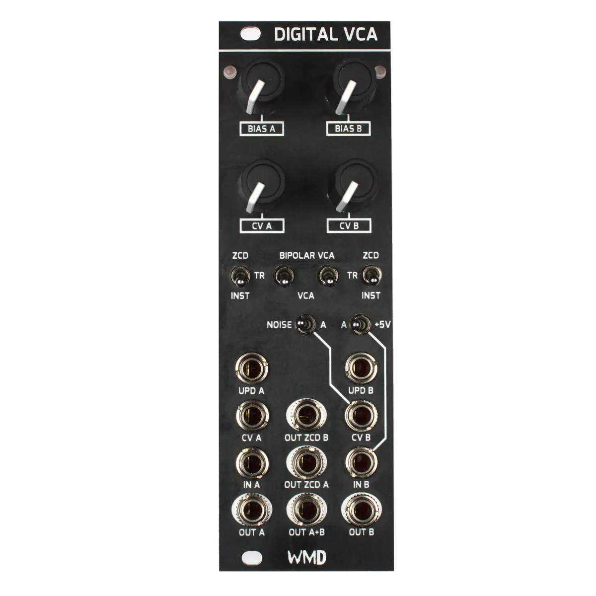
Non Traditional Fully Featured VCA
1Introduction
Thank you for purchasing the MKIII version of my classic Digital VCA. This is a design I'm super fond of for how it works behind the panel, and for its creative potential in many patches. This module combines several tools into a small package and will become a staple in your system. Thank you for supporting WMD! - William Mathewson
2Controls
- BIAS: Sets the baseline level of the VCA. In unipolar mode, fully counter-clockwise (CCW) is fully closed. In Bipolar Mode, noon is fully closed.
- CV: Jack and attenuator for CV. CCW is off, fully clockwise (CW) is full open. 5V with fully CW will open the VCA completely.
- LED: Shows the current state of the VCA. If it's off, the VCA is closed. Brighter is more open. If it's not changing, it's probably because you're in ZCD or TR mode.
3Update Modes
The ZCD/TR/INST switch controls when the VCA level is updated.
- INST: Continuous, like a normal VCA.
- TR — Trigger Mode: Updates the VCA on a rising edge (trigger or gate) into the UPD jack. The threshold for updating is +3.3V.
- ZCD — Zero Crossing Detector Mode: The signal on IN is analyzed, and every time it crosses 0V a trigger is sent to the VCA allowing it to update. This allows for fast changes in amplitude that don't click. This mode applies an amount of latency to the VCA that is at maximum 1/2 of a period of the fundamental frequency.
4Bipolar VCA / VCA Switch
VCA — normal unipolar VCA mode, like other VCAs.
BIPOLAR VCA — negative CV inverts the output signal, aka ring modulator mode. This mode moves the off point of BIAS to noon.
5Normaling
CV A has a noise source normaled to the jack. This makes the Digital VCA a Sample & Hold module in TR mode.
IN A has 5V normaled to it for use as S&H with just the TR in.
CV B can have Noise or the A CV input normaled to the jack by flipping the horizontal toggle.
IN B can have OUT A or +5V normaled to it by flipping the horizontal toggle.
CV B's Noise source is different than CV A's, so you can have two independent S&H circuits.
6Patch Examples
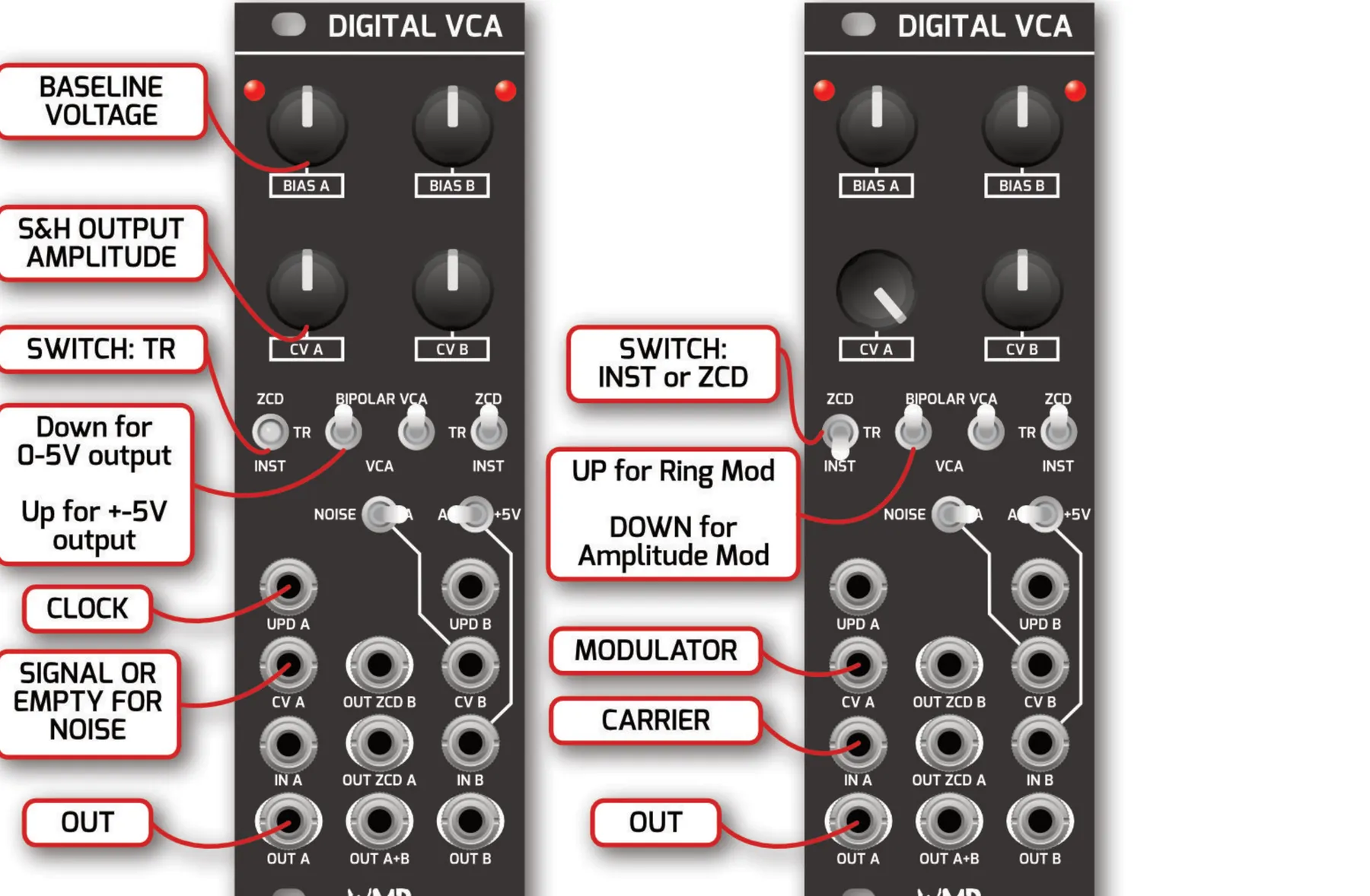
6.1Sample & Hold Patch
Connect your clock source to UPD.
CV input is the signal to be sampled. Leave unpatched for internal noise.
Turn Bias to select the baseline voltage of the output.
Turn CV to control the range of the output.
6.2Ring Mod Patch
Connect your modulator to CV.
Connect your carrier to IN.
Turn Bias to 12 o'clock.
Turn CV fully Clockwise.
Experiment with ZCD or INST modes.
Set 2nd switch to Bipolar VCA.
7Specifications
Dimensions:
- Size: 8HP
- Depth: 35mm (with cables)
- Board Height: 112mm
Power:
- +12V: 65mA
- -12V: 45mA
Inputs:
- 100k ohm impedance
- 3.3V Threshold for UPD
- CV Range: 0-5V for full opening
Outputs:
- All Outputs: 1k ohm impedance / 20Vpp range
8Videos & Patch Examples
Check out our YouTube channel for in depth videos and patch examples.