
CHANNEL SURFER

Stereo Channel FX Processor
1Introduction
Channel Surfer is a compact stereo channel processor and effects unit. It puts a full channel-strip signal path into a small module that drops cleanly into an insert point or sits anywhere in your stereo signal chain. Featuring a three-band EQ, a pair of resonant filters with drive, and a bank of nine performance effects, Channel Surfer is fully equipped to shape, perform, and add effects to any channel in your mix.
All three processing layers run at the same time and in series. A three-position toggle switch simply changes what the three knobs edit, so you can shape tone, sweep filters, and ride effects without ever leaving the signal path. A built-in ducker, assignable CV, nine presets, and LED metering make it equally at home in the studio and in live performance.
2Front Panel Overview
The three knobs and the two shift-able buttons take on different jobs depending on the position of the mode switch; the annotated panel and the labels below describe their roles.
- Mode LED Shows the active mode by color (red for EQ, white for Filters, yellow for FX), confirming the switch position. Blinks while the module is bypassed.
- FX LED Shows the selected effect's color, in every mode. While you are choosing an effect, it previews the color of the effect under the cursor.
- CV Assign Tap to bypass Channel Surfer. Also a modifier: hold CV ASSIGN and turn the bottom knob to pick an effect (FX SEL), or the middle knob to assign CV. Hold Shift and tap CV ASSIGN to step through the effects one at a time.
- Shift Hold to reveal each knob's secondary (shift) parameter in the current mode.
- Preset / Save Tap to open load mode, or hold it and turn the bottom knob for a quick load. Shift + PRESET opens save mode (SAVE). Hold PRESET for two seconds to reset the current mode, or Shift + PRESET to reset the whole module. Slots store every parameter, the selected effect, and the CV assignment.
- Mode switch Three-position toggle selecting EQ, Filters (FLTR), or FX. All three stages always run; the switch only changes what the three knobs edit.
- Top knob EQ: High shelf gain (±HIGH). Filters: Low-pass cutoff (LPF). FX: Effect amount (FX AMT). Shift: EQ: High frequency. Filters: Low-pass resonance (RES). FX: Effect Param 2 (FX2).
- Middle knob EQ: Mid bell gain (±MID). Filters: High-pass cutoff (HPF). FX: Effect character (FX1). Shift: EQ: Mid frequency. Filters: High-pass resonance (RES). FX: Effect Param 3 (FX3).
- Bottom knob EQ: Low shelf gain (±LOW). Filters: Drive. FX: Ducker amount (DUCK). Shift: EQ: Low frequency. Filters: Drive boost (BOOST). FX: Ducker release (REL).
- LED bar (9 segments) Normally a stereo output meter: the four LEDs above the center meter the left channel and the four below it the right. The top LED turns red when the left input clips, the bottom LED when the right does. Also shows soft-takeup targets, the effect picker, and the preset slots, depending on context.
- DUCK The ducker's sidechain input. Patch a gate or an audio signal here to drive the output ducking.
- CV Freely assignable CV input. Hold CV ASSIGN and turn the middle knob to choose its target; the incoming voltage adds to the knob's position.
- In L Left audio input. Patch only In L and Channel Surfer mirrors it to both channels (see Mono Input Detection).
- In R Right audio input. Patch both inputs for true stereo operation.
- Out L Left processed audio output. Patching either output takes Channel Surfer out of the insert-header loop (see Insert Bypass).
- Out R Right processed audio output.
- Mode Switch (3-position toggle): Selects what the three knobs control: EQ (left), Filters (center), or FX (right). All three processing stages keep running regardless of switch position.
- Top, Middle, and Bottom Knobs: The three main controls. Their function changes with the mode switch, and each has a secondary (shift) function accessed by holding the SHIFT button.
- CV ASSIGN Button (⏻): Press and release to toggle bypass. Also acts as a modifier. For example, hold it and turn the bottom knob to choose an effect, or the middle knob to assign CV. Holding SHIFT and tapping CV ASSIGN steps through the effects.
- SHIFT Button: Hold to access each knob's secondary parameter in the current mode.
- PRESET Button: Load the nine preset slots, or with SHIFT, save to them (SAVE). Hold it to reset the current mode to its defaults, or hold it with SHIFT to reset the whole module.
- Mode LED (top left): Shows the active mode by color (red for EQ, white for Filters, yellow for FX), confirming the switch position. Blinks while the module is bypassed.
- FX LED (top right): Shows the selected effect's color, in every mode. While you are choosing an effect, it previews the color of the effect under the cursor.
- LED Bar (9 segments): The main feedback display. Normally a stereo output meter: the center LED is the reference, the four above it meter the left channel and the four below it the right, running green, yellow, then orange as the level approaches full scale. The top LED turns red and holds briefly when the left input clips; the bottom LED does the same for the right input. The bar also shows knob pickup, the effect picker, and the preset slots, depending on context.
- Audio Inputs (L / R): Stereo signal inputs. For a mono source, patch only the left input and Channel Surfer feeds it to both channels (see Mono Input Detection).
- Audio Outputs (L / R): Processed stereo outputs.
- DUCK Input: The ducker's sidechain input.
- CV Input: Freely assignable to one of nine parameters.
3Signal Flow
Knowing the order of operations makes Channel Surfer easy to dial in. The incoming stereo signal passes through the three-band EQ, then the drive stage and the low-pass and high-pass filters, then the selected effect, and finally a safety limiter and the ducker on the way out.
Because every stage is always active, the three modes are simply three views onto the same running chain.
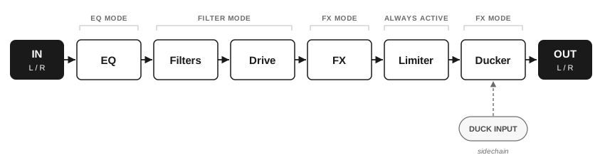
| Order | Stage | What it does |
|---|---|---|
| 1 | EQ | Three-band parametric EQ, shelving lows and highs with a sweepable mid (EQ mode). |
| 2 | Drive | Boosts the signal into the filters; a soft clipper after the filters turns the extra level into warmth and saturation (Filter mode). |
| 3 | Filters | Resonant low-pass then high-pass filters in series (Filter mode). |
| 4 | FX | One of nine selectable effects, from delay and reverb to lo-fi and frequency shifting (FX mode). |
| 5 | Safety limiter | A simple peak limiter that guards the output against runaway levels, such as an echo pushed into heavy feedback. It is a safety net rather than a creative control: it has no settings and no lookahead, so brief peaks can pass. For transparent brickwall limiting, use a dedicated limiter such as Bus Rider. |
| 6 | Ducker | Sidechain ducking driven by the DUCK CV input, applied to the output (FX mode). |
| 7 | Bypass | Crossfades between the processed signal and the dry input when you press CV ASSIGN. |
Channel Surfer's processing stages, in order. All stages run continuously; the mode switch only changes which stage the knobs edit.
4Operating Modes
The mode switch selects one of three control modes. In every mode, holding SHIFT reveals each knob's secondary parameter, and the Mode LED changes color to confirm where you are.
4.1EQ Mode
EQ mode is a three-band equalizer. Each knob sets the gain of its associated band and can boost or cut, with the low and high bands acting as shelves and the mid as a sweepable bell. Holding SHIFT turns each knob into the center-frequency control for its band, so you can place each band exactly where you need it.
| Knob | Primary: band gain | SHIFT: frequency |
|---|---|---|
| Top | High shelf gain (±15 dB) | High frequency (4 kHz to 12 kHz) |
| Middle | Mid bell gain (±15 dB) | Mid frequency (300 Hz to 7 kHz) |
| Bottom | Low shelf gain (±15 dB) | Low frequency (80 Hz to 250 Hz) |
Knob assignments in EQ mode. Hold SHIFT for the per-band frequency controls.
4.2Filter Mode
Filter mode gives you a resonant low-pass and high-pass filter in series, plus a drive stage. Use the two cutoffs together to carve a band-pass, sweep them for classic filter motion, and add drive for warmth and grit.
These filters take their inspiration from an extremely popular analog DJ mixer, and they bring that same sense of fun and playability. They shine in performance: sweep a part in to introduce it, patch CV to the cutoffs to add movement, and fit sounds with lots of harmonic content into a busy mix with precision.
Holding SHIFT reveals the resonance for each filter and the drive boost.
| Knob | Primary | SHIFT |
|---|---|---|
| Top | Low-pass cutoff (20 Hz to 20 kHz) | Low-pass resonance |
| Middle | High-pass cutoff (20 Hz to 20 kHz) | High-pass resonance |
| Bottom | Drive | Drive boost |
Knob assignments in Filter mode, following the front-panel silk. Hold SHIFT for the secondary functions.
4.3FX Mode
FX mode runs one of nine performance effects. The top knob sets the effect amount (how much of the effect you hear), the middle knob is the effect's main character parameter, and the bottom knob sets the ducker amount. Holding SHIFT reveals two more parameters for each effect on the top and middle knobs, and the ducker release on the bottom knob.
Each effect remembers its own three parameters: switch from Reverb to Chorus and back, and the reverb is exactly as you left it. All nine effects' parameters are stored in presets. The effect amount, by contrast, is a single global setting. It stays where it is when you change effects, so switching never makes the level jump.
To choose an effect, hold the CV ASSIGN button and turn the bottom knob: the LED bar shows all nine effects by color, with the first effect at the top, and the FX LED previews the effect under the cursor. Release CV ASSIGN to switch. You can also hold SHIFT and tap CV ASSIGN to step through the effects one at a time.
There is no tempo sync. These are hands-on, performance-style effects meant to be ridden in real time.
| Effect | LED color | Top: FX AMT | Middle: FX1 | SHIFT + Top: FX2 | SHIFT + Middle: FX3 |
|---|---|---|---|---|---|
| Dub Echo | White | Send | Feedback | Time | Filter |
| Reverb | Red | Send | Decay | Damping | Size |
| Phaser | Green | Depth | Rate | Mod depth | Feedback |
| Chorus | Blue | Wet level | Rate | Mod depth | Feedback |
| Tremolo | Orange | Depth | Rate | Shape | Stereo phase offset |
| Frequency Shifter | Cyan | Mix | Shift frequency | Feedback | Up/down shift mix |
| Wavefolder | Pink | Mix | Fold amount | Fold shape | Feedback |
| Analog LoFi | Purple | Amount | Filter | Wow & flutter rate | Noise |
| Digital LoFi | Yellow | Mix | Downsample | Bit depth | Jitter |
The nine effects in selection order (top of the LED bar first). The top knob's global amount (FX AMT) acts as each effect's send or mix; the FX1, FX2, and FX3 parameters are remembered separately for each effect.
Dub Echo - A short, feedback-friendly delay that smears into dubby repeats as you push feedback and time.
Reverb - Space and ambience, from a tight room to a long, damped tail.
Phaser - Sweeping notches for classic swooshing movement, from gentle to dramatic.
Chorus - Lush pitch-modulated thickening that widens and animates a static sound.
Tremolo - Rhythmic amplitude modulation, from smooth sine to choppy square, with an adjustable left/right phase offset for stereo movement.
Frequency Shifter - Inharmonic frequency shifting for metallic, clangorous, and dissonant tones.
Wavefolder - Aggressive harmonic folding that adds bite and complex overtones.
Analog LoFi - Tape-style warmth with filtering, wow & flutter, and noise for vintage character.
Digital LoFi - Downsampling, bit reduction, and clock jitter for crunchy, degraded digital textures.
4.4Bypass
Press the CV ASSIGN button (marked ⏻) at any time to bypass Channel Surfer and pass audio straight from input to output with no processing. The change is crossfaded to avoid clicks, and the Mode LED and the center LED of the bar blink to indicate the bypassed state. Bypass acts when you release the button, so holding CV ASSIGN as a modifier (to choose an effect or assign CV) never bypasses the module. The bypass state is not stored in presets.
5Ducking
Channel Surfer includes a built-in ducker that lowers the output volume in response to a signal patched into the DUCK input. It's ideal for sidechain pumping against a kick, or for ducking a processed channel under a lead. An envelope follower on the DUCK input means it responds to whatever you patch in: a gate or trigger works, and so does a full audio signal, with the ducking following that signal's level.
The ducker is controlled in FX mode: the bottom knob sets the ducking amount (how deep the level drops), and holding SHIFT sets the release (how quickly the level recovers). The attack is fixed and click-free, and the ducker is the last stage in the chain, after the effects and the safety limiter.
6CV Input
The CV input is freely assignable to any one of the nine primary parameters below; the incoming voltage is added to the knob's position. (The DUCK input is the ducker's sidechain, described above.)
To set the CV destination, hold the CV ASSIGN button and turn the middle knob to choose a target on the LED bar. Each target lights the LED bar in its mode color and in the order of the knobs, top to bottom, so you can see at a glance what you are assigning. Red for EQ, white for Filter, yellow for FX. The assignment is saved automatically and restored on power-up, and it is also stored in any preset you save. The CV input is active only when a cable is patched.
| Slot | Parameter | LED Color |
|---|---|---|
| 1 | High band gain (EQ) | EQ |
| 2 | Mid band gain (EQ) | EQ |
| 3 | Low band gain (EQ) | EQ |
| 4 | Low-pass cutoff (Filter) | Filter |
| 5 | High-pass cutoff (Filter) | Filter |
| 6 | Drive (Filter) | Filter |
| 7 | FX level | FX |
| 8 | FX parameter 1 | FX |
| 9 | Ducker amount | FX |
The nine parameters the CV input can be assigned to. Secondary (shift) parameters are not CV-assignable.
7Presets and State Saving
Channel Surfer has nine preset slots. Each stores every parameter in all three modes, including the separate settings of all nine effects, along with the selected effect and the CV assignment. Loading and saving are both done with the PRESET button and the bottom knob; on the preset page the LED bar shows the nine slots, with slot 1 at the top.
Your settings are also saved automatically in the background every 60 seconds, so Channel Surfer powers up exactly where you left it.
7.1Loading a Preset
- Enter load mode: Press and release PRESET. The LED bar shows the nine slots and the FX LED glows slowly.
- Select a slot: Turn the bottom knob to choose one of the nine slots.
- Load: Press PRESET again to load the selected slot. A white dot sweeps down the bar to confirm. To cancel instead, press SHIFT or CV ASSIGN.
7.2Saving a Preset
- Enter save mode: Hold SHIFT and press PRESET (SAVE). The LED bar shows the nine slots and the FX LED glows quickly.
- Select a slot: Turn the bottom knob to choose the slot to save to.
- Save: Hold SHIFT and press PRESET again. The whole bar flashes white to confirm. To cancel instead, press PRESET without SHIFT, or press CV ASSIGN.
7.3Resetting to Defaults
Two hold gestures return settings to their neutral defaults. Hold the buttons without touching anything else, because turning the bottom knob while holding PRESET starts a quick load instead. Releasing PRESET after a reset does not open the preset page.
Reset the current mode: hold PRESET for two seconds. The Mode LED flashes white twice. Only the mode selected on the mode switch is reset: in EQ mode, the three band gains and frequencies; in Filter mode, the cutoffs, resonances, drive, and drive boost; in FX mode, the effect amount, the current effect's three parameters (other effects keep theirs), and the ducker amount and release.
Reset the whole module: hold SHIFT and PRESET together for two seconds. Both top LEDs flash white twice. Every parameter in every mode, all nine effects' settings, the effect selection (back to Dub Echo), and the CV assignment (back to low-pass cutoff) return to their defaults.
Neither reset changes your saved presets.
8Additional Features
8.1Mono Input Detection
For a mono source, patch only the left input: Channel Surfer feeds it to both channels, so you get full stereo processing, including stereo effects, from a single cable. Patch both inputs for true stereo operation.
Detection listens for signal rather than sensing the jack. Channel Surfer starts every power-up in mono, and switches to stereo the first time it hears audio on the right input (anything above roughly -34 dBFS). A cable in the right input that carries no signal leaves it in mono. There is no LED indication of the current state.
8.2Insert Bypass
When Channel Surfer is wired to a Performance Mixer MKII channel with the ribbon cable (see Connections), it decides between the insert header and its front-panel jacks by watching its output jacks:
Both outputs empty: Channel Surfer is in the channel's insert loop. The channel's signal passes through Channel Surfer and returns to the mixer processed.
A cable in either output: Channel Surfer takes itself out of the insert loop. The mixer's insert return bypasses the module entirely, so the channel carries its own unprocessed signal, and Channel Surfer processes whatever you patch into its front-panel inputs and sends it to its front-panel outputs.
Only the output jacks are sensed; patching the inputs alone does not change the routing. This is separate from bypass (the CV ASSIGN button), which crossfades the module's own outputs to the dry input but leaves Channel Surfer in the signal path.
9Connections
9.1Power
Channel Surfer powers from your Eurorack bus board over the included 10-to-16-pin power ribbon. The 10-pin end connects to the module and the 16-pin end to the bus board in your case. The module's power header is shrouded and keyed, so the ribbon only fits one way.
9.2Audio
Channel Surfer is designed to sit at the end of a single synthesizer voice, or to insert into an individual channel of a WMD Performance Mixer MKII. There are two ways to connect it.
In-line with a synth voice. Patch the voice's output into Channel Surfer's inputs. IN L alone works for a mono voice and splits the signal to both channels, so stereo effects still apply. Take OUT L and OUT R on to your next stage, such as a mixer or Performance Mixer.
As a channel insert on the Performance Mixer MKII. Use the included ribbon cable to connect the header on the back of Channel Surfer to a channel's insert header on the back of the Performance Mixer MKII. The insert headers are labeled per channel. Wired this way, Channel Surfer sits in that channel's signal path immediately after the input gain: Gain, then the insert (Channel Surfer), then Panning, Sends, and the Volume fader / Mute.
Channel Surfer's output jacks have plug detection, so you can feed it from another source even while the ribbon is connected: patch your source into IN L / IN R and take OUT L / OUT R, and Channel Surfer disconnects itself from the insert header. The mixer channel then carries its own signal, unprocessed. Note that the signal from the mixer's insert header cannot be sent out of Channel Surfer's 3.5 mm outputs (see Insert Bypass).
10Specifications
Dimensions:
- Width: 4 HP
- Depth Including Cables: 38 mm
Power:
- Typical Power Consumption: 74 mA (+12 V), 12 mA (-12 V)
Inputs:
- Audio Inputs (L / R): stereo, with automatic mono detection; 41 kΩ impedance, 22 Vpp range
- CV Inputs: DUCK is the ducker sidechain input, CV is assignable; 100 kΩ impedance, ±5 V range
Outputs:
- Audio Outputs (L / R): processed stereo output; 470 Ω impedance, 21 Vpp range
Processing:
- 3-band parametric EQ (shelving lows/highs, sweepable mid)
- Resonant low-pass and high-pass filters with drive
- 9 selectable effects
- Sidechain ducker
- Output safety limiter
- 9 presets with automatic state saving
Audio Format:
- Sample Rate: 96 kHz
- Bit Depth: 24-bit
Features:
- Stereo multi-effects processing
- 3-band parametric EQ
- DJ-style high-pass / low-pass filters with individual resonance
- Dub echo, reverb, phaser, chorus, and more
- Ducker input for sidechaining, with amount and release control
- 24-bit / 96 kHz signal path