
BUS RIDER

Multiband Master-Bus Processor
1Introduction
Bus Rider is a compact stereo master-bus processor — a full mastering-style chain in a single Eurorack module. It is built to sit across your mix or final output and give it the polish of a dedicated mastering chain: controlled dynamics, a balanced spectrum, harmonic saturation, and clean, transparent peak limiting — all without leaving your rack.
A Linkwitz-Riley crossover splits the signal into low, mid, and high bands for independent compression and per-band level; the mid and high bands — plus as much of the low band as you choose — then run through the saturator and hard clipper, and everything recombines into a single, full-band lookahead limiter.
All three processing layers run at the same time and in series. A three-position toggle switch simply changes what the three knobs edit, so you can dial in compression, shape the band balance, and set your limiter and saturation without ever leaving the signal path. Nine presets, assignable CV, and a bank of LEDs for metering and gain-reduction feedback round out a deep tool that stays quick to use.
2Front Panel Overview
Bus Rider packs its full feature set into a compact panel. The three knobs take on different jobs depending on the position of the mode switch, while the two shift-able buttons unlock deeper functions — preset saving and loading, CV assignment, stereo linking, and a complete module bypass. The labels below describe their roles.
- Mode LED Changes color to confirm the active mode — ISO (red), Dynamics (white), Limiter (yellow). Blinks when Bus Rider is bypassed.
- Band / Status LED ISO and Dynamics: shows the band you last adjusted in its own color — High (blue), Mid (pink), Low (orange) — glowing brighter as its level rises. Limiter: lights red in proportion to how much hard clipping is happening. Hold Shift to display the limiter stereo-link state in purple: bright when linked, dim when unlinked.
- CV Assign (Link) Tap to bypass Bus Rider. SHIFT + CV ASSIGN toggles stereo link for the limiter's detector. Hold it and turn the middle knob to assign the CV input.
- Shift Hold to reveal each knob's secondary parameter. The knobs' shift roles change with the selected mode.
- Preset / Save Tap to open load mode, or hold it and turn the bottom knob for a quick load. Shift + PRESET opens save mode (SAVE). Hold PRESET for two seconds to reset the current mode, or Shift + PRESET to reset the whole module. Slots store every parameter, the CV assignment, and the stereo-link state.
- Mode switch Three-position toggle selecting ISO, Dynamics (DYN), or Limiter (LIMIT). All three stages always run. The switch only changes what the three knobs edit.
- H knob — High band ISO: High band level (kill to +12 dB, unity at noon). Dynamics: High-band compression threshold (0 to −50 dBFS). Limiter: Limiter gain (−12 to +12 dB, unity at noon). Shift: Hold Shift — ISO: Mid–High crossover (2–10 kHz). Dynamics: High-band ratio (1.5:1 to 10:1). Limiter: Output ceiling (−24 to −1 dBFS).
- M knob — Mid band ISO: Mid band level (kill to +12 dB, unity at noon). Dynamics: Mid-band compression threshold (0 to −50 dBFS). Limiter: Limiter release (10 ms to 1 s). Shift: Hold Shift — Dynamics: Mid-band ratio (1.5:1 to 10:1). Limiter: Hard-clip threshold (off, then 0 to −36 dBFS). (No shift function in ISO mode.)
- L knob — Low band ISO: Low band level (kill to +12 dB, unity at noon). Dynamics: Low-band compression threshold (0 to −50 dBFS). Limiter: Saturation amount. Shift: Hold Shift — ISO: Low–Mid crossover (80–500 Hz). Dynamics: Low-band ratio (1.5:1 to 10:1). Limiter: Low-band mix into the saturator.
- LED bar Multi-purpose meter: stereo output level with clip indication (ISO); the last-adjusted band's level and gain reduction (Dynamics); output level and limiter gain reduction (Limiter). Also shows soft-takeup targets, the preset slots, and the CV-assign menu.
- Low Cut Dedicated low-band cut CV input. A more positive voltage removes more low end; negative voltages have no effect.
- CV Freely assignable CV input. To choose its target, hold CV ASSIGN and turn the middle knob.
- In L Left audio input. Patch only this jack and Bus Rider runs in mono, feeding the signal to both channels (see Mono Input Detection).
- In R Right audio input. Patch both inputs for true stereo operation.
- Out L Left audio output. Patching either output takes Bus Rider out of the insert-header loop (see Insert Bypass).
- Out R Right audio output.
- Mode Switch (3-position toggle): Selects what the three knobs control: ISO (left), Dynamics (center), or Limiter (right). All three processing stages keep running regardless of switch position.
- Top, Middle, and Bottom Knobs: The three main band controls — Top (High), Middle (Mid), and Bottom (Low). Their function changes with the mode switch (see the table below), and each has a secondary function held under SHIFT.
- CV ASSIGN Button (⏻): Press and release to toggle bypass of all three effects. Hold SHIFT and press it to toggle stereo link for the limiter's detector. Hold it and turn the middle knob to assign the CV input.
- SHIFT Button: Hold to access each knob's secondary parameter in the current mode.
- PRESET Button: Tap to open load mode, or hold and turn the bottom knob for a quick load. Shift + PRESET is SAVE. Hold it to reset the current mode to its defaults, or hold it with SHIFT to reset the whole module.
- Mode LED (top left): Shows the active mode by color — ISO (red), Dynamics (white), Limiter (yellow) — and confirms the switch position. Blinks when the module is bypassed.
- Band / Status LED (top right): In ISO and Dynamics modes, indicates the most recently adjusted frequency band by color — High (blue), Mid (pink), Low (orange) — glowing brighter as its level rises. In Limiter mode, lights red in proportion to how much deliberate hard clipping is happening. Holding Shift shows the stereo-link state in purple: bright when linked, dim when unlinked.
- LED Bar (9 segments): The main feedback display. In ISO mode it is a stereo output meter; in Dynamics and Limiter modes it shows level and gain reduction (see each mode below). It also shows soft-takeup targets, the preset slots, and the CV-assign targets, depending on context.
- Audio Inputs (L / R): Stereo signal inputs. For a mono source, patch only the left input and Bus Rider feeds it to both channels (see Mono Input Detection).
- Audio Outputs (L / R): Processed stereo outputs.
- CV Inputs (Low Cut / CV): Low Cut is dedicated to low-band cut. The CV input is freely assignable to one of nine parameters.
| Knob | ISO | Dynamics | Limiter |
|---|---|---|---|
| Top (High) | High level SHIFT: Mid–High crossover | High threshold SHIFT: ratio | Limiter gain SHIFT: output ceiling |
| Middle (Mid) | Mid level | Mid threshold SHIFT: ratio | Limiter release SHIFT: hard-clip |
| Bottom (Low) | Low level SHIFT: Low–Mid crossover | Low threshold SHIFT: ratio | Saturation SHIFT: low mix |
What each knob controls in every mode. The primary function is on the first line of each cell; the SHIFT (secondary) function is on the second. Full ranges are in the Operating Modes tables.
3Connections
Bus Rider is a standard Eurorack module. This section covers powering it and wiring it into a WMD Performance Mixer MKII.
3.1Power
Bus Rider powers from your Eurorack bus board with a 16-to-10-pin power ribbon — the 16-pin end connects to the bus board and the 10-pin end to the module. Bus Rider's power header is shrouded and keyed, so the ribbon only fits one way, and the module's PCB is marked with a white line and a −12V indicator to line up with the −12V rail on your bus board.
3.2Basic Setup
For master-bus processing, patch Bus Rider into the master insert on whatever mixer you're using.
If your mixer has no master send/return, plug your master output into Bus Rider's inputs and run Bus Rider's outputs into your output module — or straight into an audio interface, mixer, or stereo DI box.
In-line with a synth patch, Bus Rider works anywhere in the signal path — we recommend placing it at the end of a synth chain to apply its full processing to that individual track.
3.3Connecting to a Performance Mixer MKII
Bus Rider is designed to run with a WMD Performance Mixer MKII, and there are two ways to connect it. The PM MKII has no master insert header (a hardware limitation), so master-bus use requires patch cables.
On the master bus (patch cables). By default, Bus Rider processes the mixer's full stereo mix. Using regular patch cables, send the Performance Mixer's master insert to Bus Rider's IN L and IN R, and return OUT L and OUT R to the master insert. The whole mix then passes through Bus Rider on its way to the main outputs.
Hard-wired to one channel (ribbon cable). To insert Bus Rider into a specific channel instead, use the included ribbon cable to connect the header on the back of Bus Rider to that channel's insert header on the back of the Performance Mixer MKII — the mixer's insert headers are labeled per channel. Wired this way, Bus Rider sits in that channel's signal path immediately after the input gain: Gain, then the insert (Bus Rider), then Panning, Sends, and the Volume fader / Mute.
Bus Rider's output jacks have plug detection, so you can use the module with another source even while the ribbon is connected: patch your source into IN L / IN R and take OUT L / OUT R, and Bus Rider disconnects itself from the insert header — the mixer channel then carries its own signal, unprocessed. Note that the signal from the mixer's insert header cannot be sent out of Bus Rider's 3.5 mm outputs, and that the switch-over can take up to 8 seconds (see Insert Bypass).
4Signal Flow
Understanding the order of operations makes Bus Rider easy to dial in. The incoming stereo signal is split into Low, Mid, and High bands by a Linkwitz-Riley crossover. Each band is compressed independently, then trimmed in level (ISO). The mid and high bands — plus as much of the low band as you choose — pass through the saturator and hard clipper, the rest of the low band rejoins them clean, and the full-band result passes through a final lookahead limiter on the way out.
Because every stage is always active, the three modes are simply three views onto the same running chain.
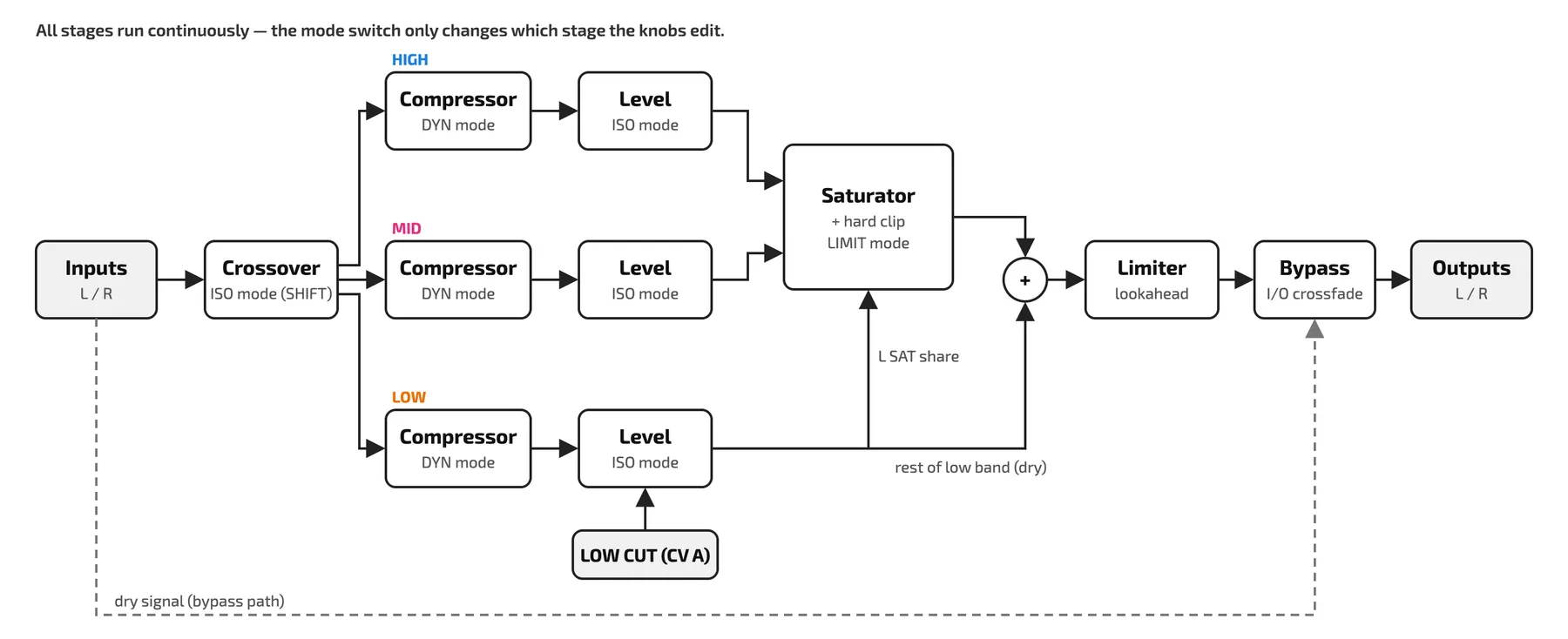
| Order | Stage | What it does |
|---|---|---|
| 1 | Crossover | Splits the stereo input into Low / Mid / High bands with a 4-pole (24 dB/oct) Linkwitz-Riley crossover. Crossover points are adjustable in ISO mode. |
| 2 | Multiband compressor | An independent compressor on each band, with its own threshold and ratio (Dynamics mode). |
| 3 | ISO (band level) | Per-band level, from a full kill to +12 dB (ISO mode). Use it to rebalance the spectrum after compression, to correct the overall tonal balance of a mix or for a room, or creatively — for example, cutting all the lows like a DJ. |
| 4 | Saturator and hard clip | Adds harmonic drive and warmth, followed by an optional hard clipper; the low band is kept out to preserve the bass but can be mixed back in (Limiter mode). |
| 5 | Lookahead limiter | A fast, clean output limiter with adjustable gain, ceiling, and release (Limiter mode). |
| 6 | Bypass | Crossfades between the processed signal and the dry input when you press CV ASSIGN. |
Bus Rider's processing stages, in order. All stages run continuously; the mode switch only changes which stage the knobs edit.
5Operating Modes
The mode switch selects one of three control modes — ISO, Dynamics, and Limiter. In every mode, holding SHIFT reveals each knob's secondary parameter, and the Mode LED changes color to confirm where you are. The LED bar and the Band LED change what they display with the mode, as described in each section below.
The module can be bypassed in any mode, letting you quickly compare the dry, unaffected mix against the processed sound.
Animation: the knob's indicator turns until it lines up with the recorded takeup position marked above it; when they meet, the marker fades away as the new function engages. The sequence then repeats.
5.1ISO Mode
ISO mode is a three-band isolator. Each knob sets the level of one band: unity at noon, up to +12 dB clockwise, and down to a full kill fully counterclockwise. Use it to rebalance a mix after compression, to correct the overall tonal balance for a mix or a room, or creatively — pull the low knob all the way down to cut the lows like a DJ, then bring them back in. Holding SHIFT turns the top and bottom knobs into the crossover-frequency controls, so you can decide exactly where the bands split.
LED bar: a stereo output meter. The center LED is the reference; the four above it meter the left channel and the four below it the right, running green, yellow, then orange as the level approaches full scale. The top LED turns red and holds briefly when the left input clips; the bottom LED does the same for the right input.
Band LED: shows the color of the band you last adjusted, glowing brighter as that band's incoming level rises.
| Knob | Primary — band level | SHIFT — crossover |
|---|---|---|
| Top | High band level (kill to +12 dB; 0 dB at noon) | Mid–High crossover (2 kHz to 10 kHz) |
| Middle | Mid band level (kill to +12 dB; 0 dB at noon) | — |
| Bottom | Low band level (kill to +12 dB; 0 dB at noon) | Low–Mid crossover (80 Hz to 500 Hz) |
Knob assignments in ISO mode. Hold SHIFT for the secondary (crossover) functions.
5.2Dynamics Mode
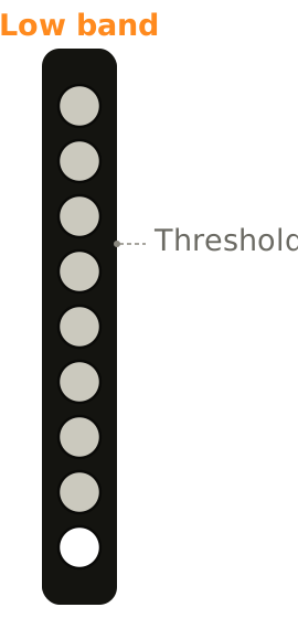
Dynamics mode gives each band its own compressor. The three knobs set the compression threshold per band, and holding SHIFT sets the ratio per band. Turning a threshold knob clockwise lowers the threshold, bringing that band's compressor in sooner; raising the ratio increases how hard it clamps down once engaged.
The compressors use level (RMS) detection with a soft knee and automatic makeup gain, and their attack and release times are tuned per band — faster on the highs, slower on the lows — for natural-sounding multiband control. Each compressor always responds to both channels together, preserving the stereo image.
LED bar: shows the band you last adjusted. White lights meter that band's incoming level from the bottom up (−50 dBFS to full scale), while the band's own color — orange for Low, pink for Mid, blue for High — shows its gain reduction from the top down (up to 24 dB), so you can see exactly how hard the band is working. Touch another band's knob to switch the display to that band.
Band LED: as in ISO mode, shows the color and incoming level of the band you last adjusted.
| Knob | Primary — threshold | SHIFT — ratio |
|---|---|---|
| Top | High band threshold (0 to −50 dBFS) | High band ratio (1.5:1 to 10:1) |
| Middle | Mid band threshold (0 to −50 dBFS) | Mid band ratio (1.5:1 to 10:1) |
| Bottom | Low band threshold (0 to −50 dBFS) | Low band ratio (1.5:1 to 10:1) |
Knob assignments in Dynamics mode. Hold SHIFT for the per-band ratio.
5.3Limiter Mode
Limiter mode controls the output stage: a saturator and hard clipper for harmonic warmth, glue, and deliberate clipping, followed by a lookahead limiter for transparent level control. Use the limiter gain to push level into the ceiling and catch peaks cleanly — the lookahead design means the limiter catches transients without overshoot — and add saturation to taste for drive and density.
Holding SHIFT reveals the secondary controls: the limiter's output ceiling, the hard-clip threshold, and how much of the low band is fed into the saturator (keep it out to preserve a clean low end, or mix it in for a more aggressive sound). The hard clipper is off with its knob fully counterclockwise; turning it up lowers the clip threshold, down to −36 dBFS. It acts only on the signal passing through the saturator, so any low end you keep out of the saturator is never clipped.
LED bar: white lights meter the output level from the bottom up (−50 dBFS to full scale), and yellow lights show the limiter's gain reduction from the top down (up to 24 dB).
Band LED: lights red in proportion to how much deliberate hard clipping is happening — dark when the hard clipper is off or the signal stays below its threshold, brighter the further the signal is driven past it.
| Knob | Primary | SHIFT |
|---|---|---|
| Top | Limiter gain (−12 to +12 dB; 0 dB at noon) | Output ceiling (−24 to −1 dBFS) |
| Middle | Limiter release (10 ms to 1 s) | Hard-clip threshold (off, then 0 to −36 dBFS) |
| Bottom | Saturation amount | Low-band mix into saturator |
Knob assignments in Limiter mode. Hold SHIFT for the secondary functions.
5.4Bypass
Press and release the CV ASSIGN button (marked ⏻) at any time to bypass Bus Rider and pass audio straight from input to output with no processing. The change is crossfaded to avoid clicks, and the Mode LED blinks to indicate the bypassed state (in ISO mode, the center LED of the bar blinks too). Bypass acts when you release the button, so using the button for the stereo link or CV assignment never bypasses the module. The bypass state is not stored in presets.
6CV Inputs
Bus Rider has two CV inputs.
The first — the left jack, labeled LOW CUT — is dedicated to low-band cut: a positive voltage is subtracted from the low ISO knob, so more voltage removes more low end, making it easy to cut the lows with an external CV source. Negative voltages have no effect. With the low knob at noon, about +2.5 V kills the low band completely.
The second — the right jack, labeled CV — is freely assignable to any one of the nine primary parameters listed below; the incoming voltage is added to the knob's position.
To assign it, hold the CV ASSIGN button and turn the middle knob to choose a target on the LED bar, then release it. The bar's segments are arranged by knob position and mode color, so an assignment is easy to place and remember. The assignment is stored with your settings and in presets. Each input passes voltage only when a cable is patched.
| Slot | Parameter |
|---|---|
| 1 | High band level (ISO) |
| 2 | Mid band level (ISO) |
| 3 | Low band level (ISO) |
| 4 | High band compression threshold |
| 5 | Mid band compression threshold |
| 6 | Low band compression threshold |
| 7 | Limiter gain |
| 8 | Limiter release |
| 9 | Saturation amount |
The nine parameters the CV input can be assigned to. Secondary (shift) parameters such as crossover frequencies and ratios are not CV-assignable.
7Presets and State Saving
Bus Rider has nine preset slots. Each stores every parameter in all three modes, the CV assignment, and the stereo-link state. Loading and saving are both done with the PRESET button and the bottom knob; on the preset page the LED bar shows the nine slots, with slot 1 at the top.
Your settings are also saved automatically in the background, so Bus Rider powers up exactly where you left it — there is no need to manually store your working state before turning the system off.
7.1Loading a Preset
- Enter load mode: Press and release PRESET. The LED bar shows the nine slots and the Band LED glows slowly.
- Select a slot: Turn the bottom knob to choose one of the nine slots.
- Load: Press PRESET again to load the selected slot. A white dot sweeps down the bar to confirm. To cancel instead, press SHIFT or CV ASSIGN.
7.2Saving a Preset
- Enter save mode: Hold SHIFT and press PRESET (SAVE). The LED bar shows the nine slots and the Band LED glows quickly.
- Select a slot: Turn the bottom knob to choose the slot to save to.
- Save: Hold SHIFT and press PRESET again. The whole bar flashes white to confirm. To cancel instead, press PRESET without SHIFT, or press CV ASSIGN.
7.3Resetting to Defaults
Two hold gestures return settings to their neutral defaults. Hold the buttons without touching anything else — turning the bottom knob while holding PRESET starts a quick load instead. Releasing PRESET after a reset does not open the preset page.
Reset the current mode — hold PRESET for two seconds. The Mode LED flashes white twice. Only the mode selected on the mode switch is reset: in ISO mode, the three band levels return to unity and the crossovers to their default points; in Dynamics mode, every threshold returns to 0 dBFS and every ratio to 1.5:1 (no compression); in Limiter mode, the gain returns to 0 dB, the ceiling and release to their defaults, and saturation, hard clip, and low-band mix to off.
Reset the whole module — hold SHIFT and PRESET together for two seconds. Both top LEDs flash white twice. Every parameter in every mode returns to its default, the CV assignment returns to high band level, and the stereo link turns off.
Neither reset changes your saved presets.
8Stereo Linking and Mono Handling
8.1Limiter Stereo Link
The output limiter can run stereo-linked or independent. When linked, the left and right channels share a single gain-reduction value, preserving the stereo image as the limiter works. When unlinked (the default), each channel limits on its own, which can act more aggressively on a lopsided mix. The multiband compressors are always linked. Hold SHIFT and press CV ASSIGN at any time, in any mode, to toggle the link; while SHIFT is held, the Band / Status LED shows the current state in purple — bright when linked, dim when unlinked. The link state is stored in presets.
8.2Mono Input Detection
For a mono source, patch only the left input: Bus Rider feeds it to both channels, so you get full processing without needing a stereo source. Patch both inputs for true stereo operation.
Detection listens for signal rather than sensing the jack. Bus Rider starts every power-up in mono, and switches to stereo the first time it hears audio on the right input (anything above roughly −34 dBFS). A cable in the right input that carries no signal leaves it in mono. There is no LED indication of the current state.
8.3Insert Bypass
When Bus Rider is hard-wired to a mixer channel with the ribbon cable (see Connecting to a Performance Mixer MKII), it decides between the insert header and its front-panel jacks by watching its output jacks:
Both outputs empty — Bus Rider is in the channel's insert loop. The channel's signal passes through Bus Rider and returns to the mixer processed.
A cable in either output — Bus Rider takes itself out of the insert loop. The mixer's insert return bypasses the module entirely, so the channel carries its own unprocessed signal, and Bus Rider processes whatever you patch into its front-panel inputs and sends it to its front-panel outputs.
Only the output jacks are sensed — patching the inputs alone does not change the routing. This is separate from bypass (the CV ASSIGN button), which crossfades the module's own outputs to the dry input but leaves Bus Rider in the signal path.
9Specifications
Dimensions:
- Width: 4 HP
- Depth (with cables): 38 mm
Power:
- Typical draw: +12 V 74 mA, −12 V 12 mA
Inputs:
- Audio Inputs (L / R): 41 kΩ impedance, 22 Vpp range; automatic mono detection
- CV Inputs (Low Cut / CV): 100 kΩ impedance, ±5 V
Outputs:
- Audio Outputs (L / R): 470 Ω impedance, 21 Vpp range
Processing:
- 3-band Linkwitz-Riley crossover, 4-pole (24 dB/oct)
- Multiband compressor with per-band threshold and ratio
- Per-band level from full kill to +12 dB
- Saturation with adjustable low-band mix, and hard clipper
- Lookahead limiter (1.3 ms lookahead)
- 9 presets with automatic state saving
Audio Format:
- Sample Rate: 96 kHz
- Bit Depth: 24-bit
Features:
- Lookahead limiter
- 3-band isolator EQ
- Multiband compression